For this project I am going to use OpenSCAD to model, I hope, a dog/person-proof retaining wall, and to build modular retaining-wall sections. Then I will discuss, in a little more detail than I have been, the setup of the 3D printer and a little commentary on why I use those settings. In addition, I will also discuss the acetone-vapor bath, finishing the product and protecting the model.
NOTE: Scroll to the end of the article for all related downloads.
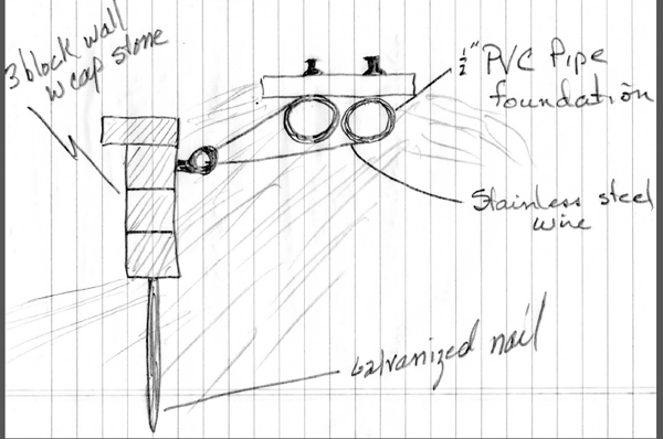
I always make a sketch of the model to memorialize my ideas and concepts. They are hand drawn and quick, and do not take very long. The sketch (photo 2) shows the wall and how I plan to secure it to prevent it from being pushed or falling over.
OpenSCAD is sometimes referred to as the programer’s solid-3D CAD modeler. That is because you are not doing the design graphically, but typing in the model using a specific syntax. It is quicker and easier to change objects using this method than a graphically designed object. Please think of this as learning a different language. It will take some time but, the more you expose yourself to the language, the easier it becomes.
Modules
A module is a sub-routine that builds objects that can be used over and over. Since we really only have two objects — the capstone and the block — we can build the retaining wall using the two modules, repeating as necessary, as many times as we want.
There are three modules in the OpenSCAD program: roundedcube, block, and capstone. I downloaded the complicated roundedcube module to make the bullnose capstone. I will not explain this module, as it is very complicated, but it works. Let’s instead look at the other two.
Module block
This module defines the blocks that make up the wall.
//The block prototype is D”xW”xH”
//Grout line is grout_line” all around
module block() {
union() {
//Create block
translate([grout_line*mm_inch/scale,
grout_line*mm_inch/scale,
0])
cube([((block_H-2*grout_line)*mm_inch/scale),
((block_W-2*grout_line)*mm_inch/scale),
(block_D*mm_inch/scale)]);
//Create grout line
translate([0,
0,
0])
cube([(grout_H*mm_inch/scale),
(grout_W*mm_inch/scale),
((grout_D-grout_line)*mm_inch/scale)]);
}
}
Before we go much further, at the very beginning of the program I define some variables that will be used throughout the program. You can change these variables and, every time the variable is referenced, it will change. This way you can easily change sizes, lines, and other features.
mm_inch = 25.4;
scale = 20.32;
grout_line = 5/8;
block_D = 8; //block depth
block_W = 16; //block width
block_H = 8; //block height
grout_D = 8; //grout depth
grout_W = 16; //grout width
grout_H = 8; //grout height
capstone_D = 12; //capstone depth
capstone_W = block_W; //capstone width
capstone_H = 4; //capstone height
capstone_grout_D = block_D; //capstone grout height
The variable mm_inch is the conversion from inches to mm since OpenSCAD does everything in mm. “Scale” is the scale that I am modeling, in this case 1:20.32. If you did not like this scale, you can change this variable and the whole model will be set to, say, 1:24 scale automatically. Next is the grout line. I choose this number based on experimentation. This size is what looks good to me, but you may want to change it to be larger or smaller.
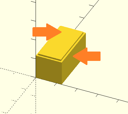
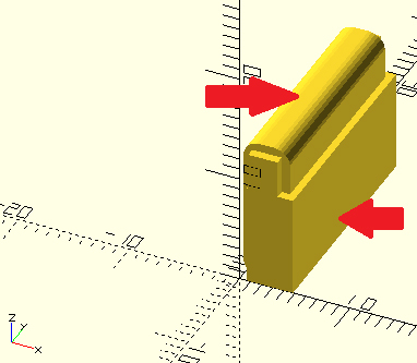
Next, I am going to create the actual block. (Shown by the top arrow in red, photo 3.) Since the actual block is not at the origin (it is inset by the grout line), we translate the block in a little to make room for the grout line. translate([grout_line*mm_inch/scale, grout_line*mm_inch/scale ,0]) Note: If you look at the graphics screen, you will notice a triad that gives the X, Y, Z axis. Looking at the translate instruction, it is referenced by translate([X, Y, Z]); The first variable moves in the X direction, the next moves in the Y direction, and the last moves in the Z direction.
//Create block
translate([grout_line*mm_inch/scale,
grout_line*mm_inch/scale,
0])
cube([((block_H-2*grout_line)*mm_inch/scale),
((block_W-2*grout_line)*mm_inch/scale),
(block_D*mm_inch/scale)]);
If you purchase a concrete block, you will find that it is not the size advertised. They allow for a grout line to make up the difference. Notice that I am subtracting a grout line on each side. We will add the grout line next.
The grout line is the actual size of the finished block. Therefore, the only place we subtract a grout line is in the Z direction. This way we have the “face” of the block exposed. This is pointed out by the lower red arrow in the photo.
//Create grout line
translate([0,
0,
0])
cube([(grout_H*mm_inch/scale),
(grout_W*mm_inch/scale),
((grout_D-grout_line)*mm_inch/scale)]);
There is no translation at this point, since we want the edge of the block to be at the origin. Then we have to define the cube that makes up the grout line.
One thing to mention is that at the very beginning of this module we see the instruction:
union() {
.
.
}
“Union” means to sum all parts of the following objects. This combines the block into one part; not two separate parts.
Now for the bull nose capstone:
//The cap stone prototype is capstone_W x capstone_D x capstone_H”
//Grout line is grout_line on the bottom and sides
module cap_stone() {
union() {
//Create the cap stone
translate([0,
grout_line*mm_inch/scale,
0])
roundedcube([((capstone_H-grout_line)*mm_inch/scale),
((capstone_W-2*grout_line)*mm_inch/scale),
((capstone_D-2*grout_line)*mm_inch/scale)],
false, 1.5, “y”);
//Create grout line
translate([grout_line*mm_inch/scale,
0,
0])
cube([((capstone_H-grout_line)*mm_inch/scale),
(capstone_W*mm_inch/scale),
((capstone_grout_D-grout_line)*mm_inch/scale)]);
//Create left grout line
translate([grout_line*mm_inch/scale,
0,
0])
cube([((capstone_H-3*grout_line)*mm_inch/scale),
(capstone_W*mm_inch/scale),
((capstone_D-3*grout_line)*mm_inch/scale)]);
}
}
The top arrow points (photo 4) to the object generated by the function roundedcube([…]);. I use a variable to define the size as before, although there are two grout cubes. One is the body of the grout that the lower red arrow points to and the next is the very small grout area that you see next to the bull nose. I had to make those two separate grout cubes because you do not want grout on the exposed area under the bull nose. Please explore this module further. If you have somewhat of an understanding of the module block, this one may take a little more exploration but it should come to you.
Make a copy of these files and explore changing the variables to see what it does to the part.
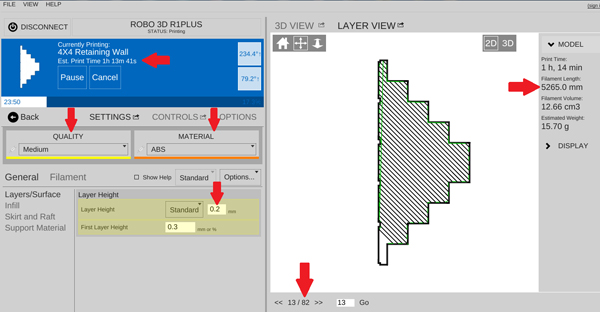
With my 3D printer, I used white ABS filament from Matterhackers.com. Under the “settings” tab I selected “ABS” and “Medium quality.” I tried using low quality to get some texture to the face of the block, but the grout lines did not come out right because of the resolution of the low-quality print. Photo 5 is a screenshot of the settings.
The very top red arrow on the left shows the print time: 1h 13m 41s. This is only an estimate. Under that and to the left is where you set the print quality to “Medium” and next to that the material is “ABS.” Below the material you will see an arrow pointing to the layer height: 0.2mm. If the quality of the print was chosen as “High,” this value would be 0.1mm. “Low” would have been 0.3mm.
In the bottom center is shown how many extrusion movements are to be made. This is not the number of layers. Sometimes the slicer program, which cuts the object up into layers so the 3D printer can lay down a layer at a time, puts in several extruder movements per layer. I have no idea why but at least you can see the progress: I am on 13 out of 82 extruder movements.
Next, in the upper-right-hand corner is the estimate of the number of millimeters of filament that is going to be used. Since the filament that I am using runs about 10¢ per meter, this is going to cost 52¢ in material.
Once the part is printed and I remove some of the flashing with an X-acto knife, it is ready for the acetone-vapor bath. The purpose of the vapor bath is to melt all the layers together that did not bond during printing. This makes for a very strong part of almost solid ABS. You cannot soak the part in acetone because that will just melt the whole part. A vapor bath gently covers the area and lets the bonding take place.
To make the acetone-vapor-bath equipment you will need:
1 gallon, empty steel paint bucket
Several (about eight) small magnets
2 metal flower frogs
Paper towels
Timer
Acetone
Cover the inside of the paint bucket with the paper towels, holding the towels down with the magnets. Make at least two layers of the paper towel in the bucket. With the towels held down by the magnets, you can pour in several ounces of acetone. Rotate the bucket on its side to wet all the paper towels with acetone. Keep it away from your face; I don’t like the smell of the vapors. Next, lay the paint-can cover down flat, with the inside of the cover facing up. Place the two metal flower frogs on top of the lid and place your part on the frogs. Now carefully turn the paint bucket upside down over the parts and in line with the lid. Do not secure the lid to the bucket, just set the bucket on top of the lid to capture the fumes. Set the timer to 10-40 minutes. The time depends on temperature and humidity. The part should be shiny after the appropriate amount of time, which means all the layers have collapsed into one solid piece. Experiment with the time to determine what is best for your area. After the time has elapsed, remove the paint can, reset the timer to 10-20 minutes, and leave the part exposed to the air to dry. It is still sticky at this point, so do not pick up the part just yet.
Prepare for painting
Painting a shiny part might be difficult. Sometimes you need to rough up the surface to get the paint to stick. Again, go to the acetone. This time, get a little acetone on the rag and quickly rub the surface. It should turn dull and rough. You are now ready to put some sections together or apply paint.
Decide how you want your sections to go together. Some sections might want to stand alone, some sections you will want to glue together.
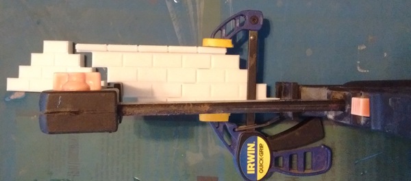
For my first assembly (photo 6), I am going to take one section that was printed from the file 4×4 retaining wall.stl and glue on two sections of 4x4stl; one on each side of it.
Painting
The first thing I did was to give the blocks a “wash” coat of FolkArt Dove Gray acrylic paint. The very light coat was used to establish a base color. After that dried, I gave the blocks another coat of the paint. I tried to let a little of the ABS white show through, but not too much. Then, with a fine brush, I painted the grout lines with Testors GL Gray to give them a little contrast. Next, I sprayed everything with three coats of Krylon’s Satin Clear Polyurethane to try to protect the model.
Hardware
As is shown in my sketch, I plan on putting some long nails (I used 16d) on the bottom of the retaining walls to keep the bottom from sliding. I will also use some eyes with stainless steel or galvanized wire to wrap around the PVC trackbed foundation that I have. When you drill the holes for the nails, you will notice the drill hitting some “soft-spots”. That is where the printer did not put down much material (called infill). This is OK; fill the hole with epoxy and it will hold just fine.
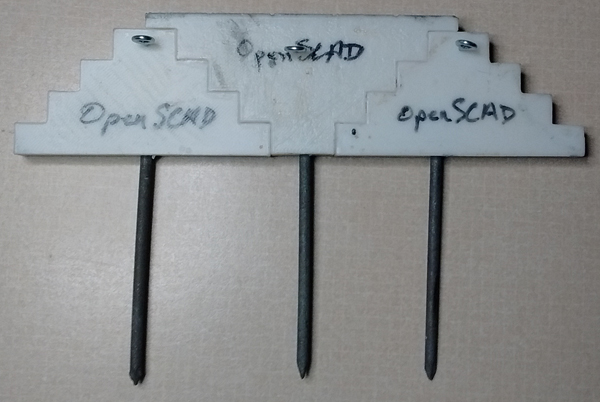
Photo 7 is the finished section of wall with the eyelets and nails.
Using OpenSCAD can be a little scary at first but, with the example given, I hope that you will experiment and learn more about this 3D modeling program. I need to make a couple more sections, then install them and see how they withstand man and beast!