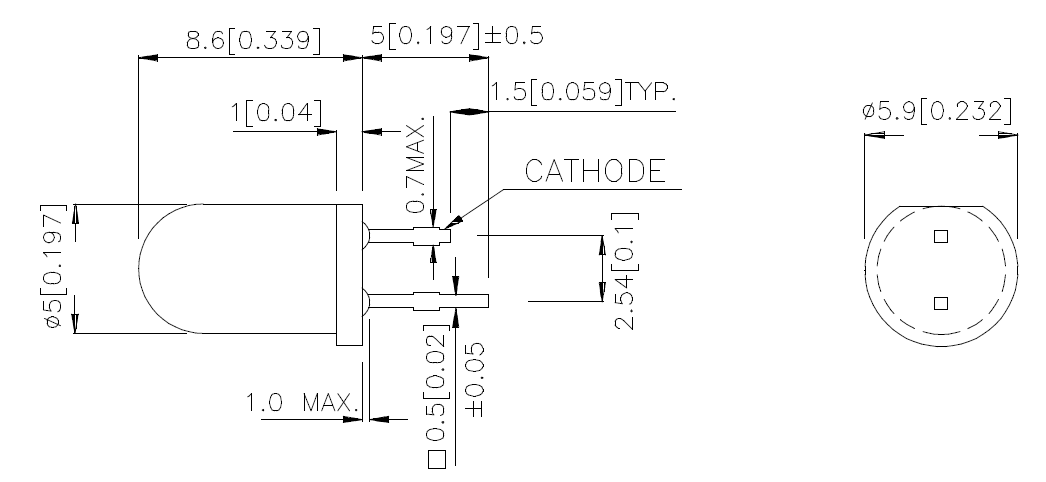
Railroad signals have been around for a very long time. Signals are an important safety feature on railroads. As usual, I enjoy the journey of making my own. These signals may not be to scale — I just need them to look right on my railroad. Using commonly available T-1 ¾ LEDs, the design revolves around those dimensions and the signal should come out close.
NOTE: All downloadable files are in a box at the end of this article.
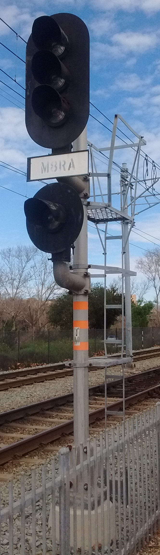
I was down in San Diego a while ago and took some pictures of the signals that they are using on the San Diego Trolley (Photo 1). I’ll use these as the prototypes for my signals. As usual, I have to guess about the dimensions but, in the end the question is, does the signal look correct for the scale that I am using?
I will be using Solidworks as the CAD program. I am fluent in its use and I can get things done much faster that way. I realize that most people will not have access to this program but, with a little bit of work, you can do the same thing in openSCAD, tinkerCAD, Sketchup, or your favorite CAD program.
Dimensions
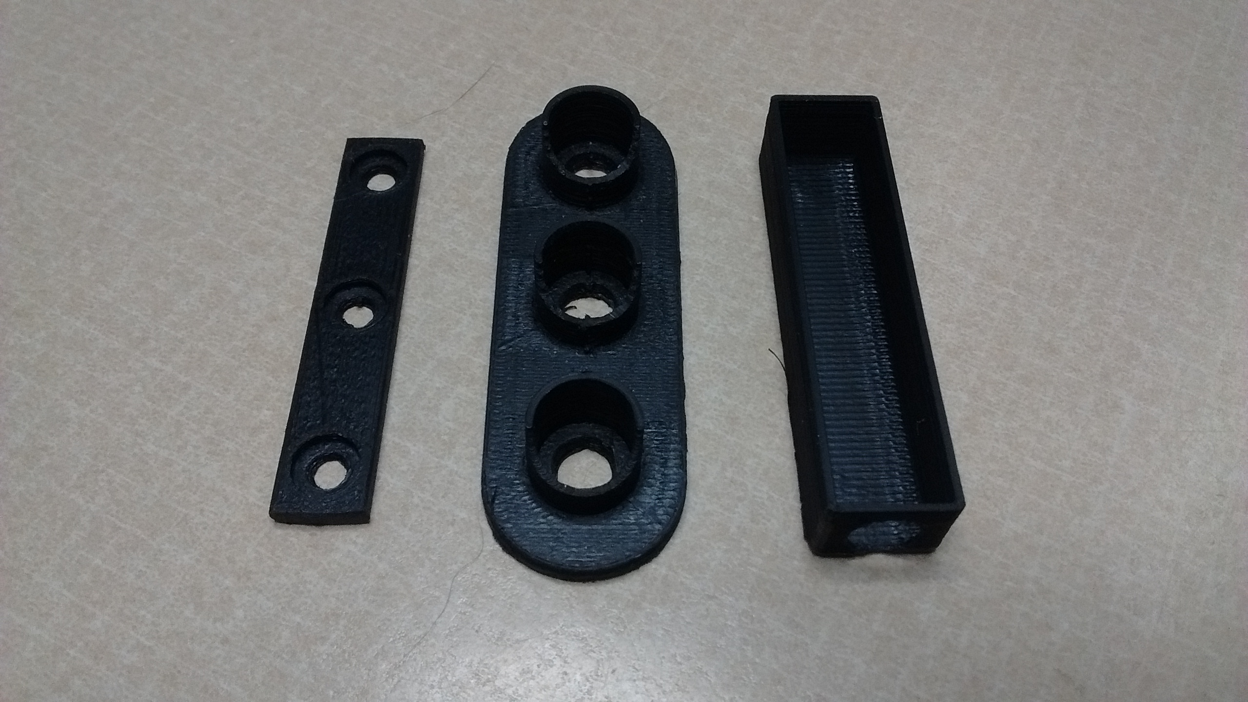
I am going to guess the signal back plate is about 45” high and about 15″ wide, and I am using 20.32 as my scale. In this scale, the signal back plate is about 2.2″ x 0.74″. I have to make 5mm (0.197″) holes for the LEDs and include a shade hood around the lights to match the prototypes. (File: Face and Shade.stl) I also made a backing plate to keep the LEDs in place in the signal housing. (File: Backer Plate.stl) Behind that is the cover for everything. (File: Box.stl) (Note the hole in the bottom of the cover for the support pole in photo 2.)
As seen in the trolley-signal photo, there is a support for each signal head that extends from the main pole. There is a short 90° bend in each support pole. Initially I used ¼” aluminum tube and a tubing bender from Harbor Freight. The tube crimped badly and was basically unusable. I also tried steel, but with no satisfactory results. I happened to be at a local auto parts store and asked the salesman for a solution. He sold me a stainless-steel ¼” brake line that he guaranteed would not kink if I used the bender. I tried it and found that he was correct. I now have a solution for bending tubing.
In the trolley-signal photo (photo 1), there is a coupler that secures the bent tubing to the support pole. Time to get out the 3D printer again. After a quick design session, I started printing and got a perfect coupler. (File: pole extrusion.stl)
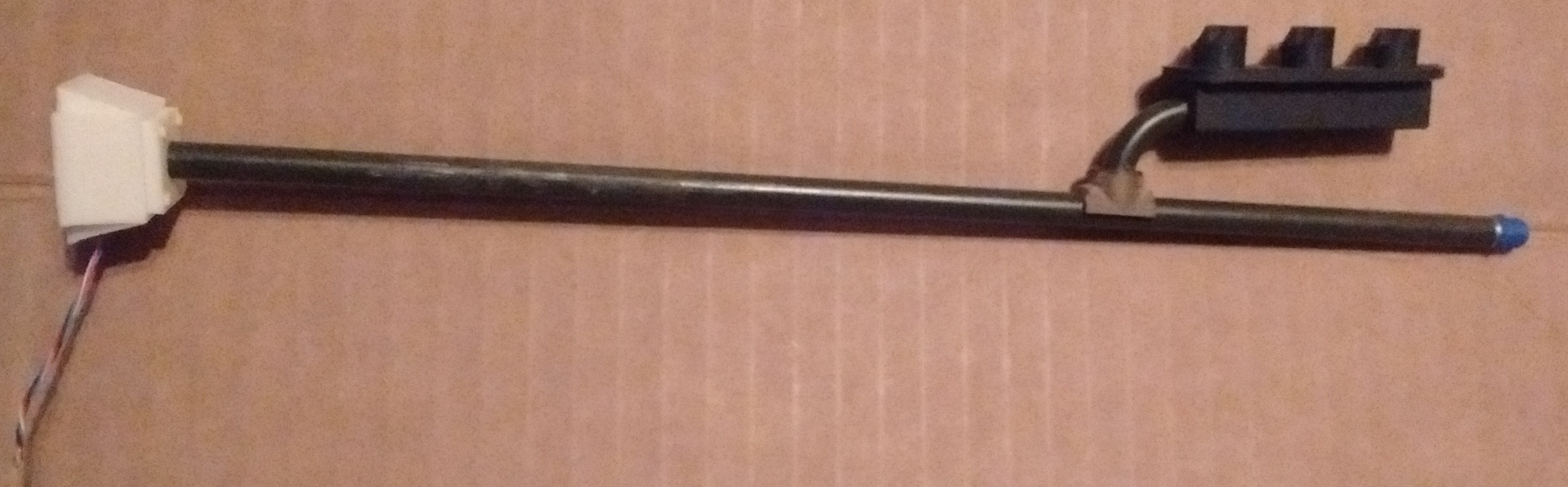
Now I had to make the pole itself. I cut 10” off the brake line and had to drill a hole in it for the wires, then add a 3D printed top. (File: Pole Cap.stl) A spot 3” down from the top appeared to be a good place to drill the hole. Since the inside diameter of the brake line is 0.175”, I used a 0.173” drill.
The wires for the LEDs feed through this hole. I used a small clamp to keep everything in place (photo 6).
To glue the arm coupler to the pole, I used a CA glue and filler called Q-Bond, from K TOOL International. I used the gray filler for metal. It is more than a little tricky to use but it bonds great to the stainless-steel brake line.
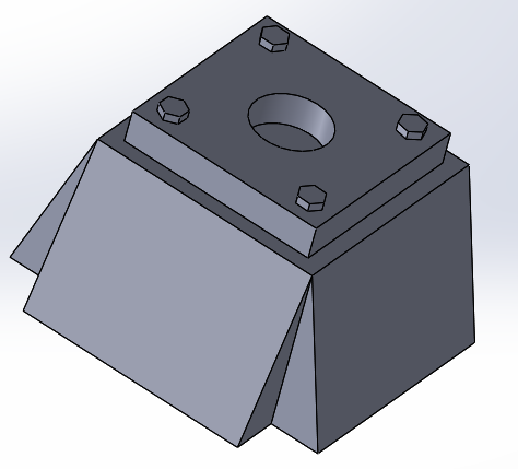
The pole must fit into a base that will hold everything up (photo 7). Ideally, it must be strong enough to hold the signal in bad weather, especially wind. I made this so it can be buried in the ground about ½” and the wings should prevent it from rotating.
I drilled halfway down to hold the pole, and laterally so the wires can exit.
I test fitted everything before painting and gluing the signal together.
In photo 8, some of the parts seem a little askew. That is because I have not glued them together or painted anything yet. When I glued everything together, I used alignment tools to make sure everything is square.
Summary
The signal is by no means complete. I still have to build the ladders, safety structure, and control box. Inside the control box will be my solar-charged battery, LED drivers, and WiFi infrastructure so that I can automate the signals. This project should be completed by the next article, barring any unforeseen problems. If you have any suggestions, comments, or questions about the dimensions, how I did this, or anything else, I would like to hear from you. Please post feedback in our forum thread. I am always in the mood to learn something new.