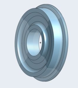
Last time I 3D printed the wheel made in a solid modeling program called Onshape and I didn’t like the results. I redesigned the wheel to make it more aesthetically pleasing and to better meet my needs.
Instead of walking through the steps that I took to create this new, improved wheel, I will show you how to create a dimensioned drawing of the part. Your homework assignment is to use the dimensions and create your own wheel that suits your needs.
Creating a dimensioned drawing
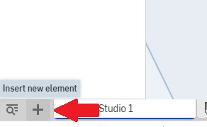
Creating a dimensioned drawing is easier than creating the part. If you take your mouse and “hover” over the “+” sign in the lower left hand corner of the part drawing, as before a help text box will appear as shown by the red arrow. The “+” sign allows you to add a new element such as a drawing. Left click on the arrow and you will get the following pop-up window:
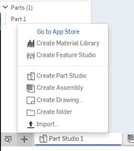
Left click on the “Create Drawing…” to start to create the drawing.
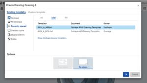
You will get the following pop up window (top image) asking you to select a drawing template. There are two drawing templates that you can use; millimeters or inches. I usually use millimeters for my work but in this case I will select the template ANSI_A_INCH.dwt. Click on OK and the drawing, shown in the bottom image will appear.
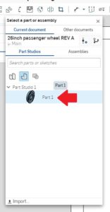
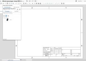
We are going to want to select the part for this drawing. There are many other options, but let us just do the part right now. The red arrow in the top image shows that we need to select “Part 1”.
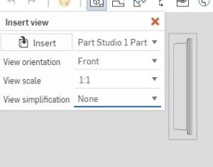
Once we click on “Part 1” we get the “insert view” window that provides several selections as shown in the bottom image.
![]()
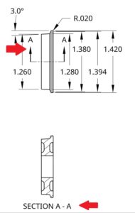
I have inserted two views that I would like to see; that of the side of the wheel and the front of the wheel. I will use the “dimension” icon (red arrow points to dimension icon) to see the dimensions of the part that I built. I will click on the dimension icon and then select a line I want dimensioned. The line will turn a different color showing that it is highlighted.
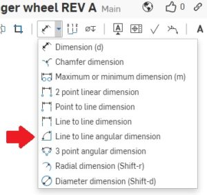
While linear dimensioning is straight forward, I want to also get the angular dimension of the wheel. The dimension icon is a pull-down icon giving several dimensioning options as shown in the top image.
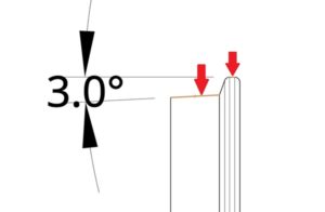
By choosing the “Line to line angular dimension”, I will be zooming into the area of interest using the scroll wheel on my mouse. Now I will pick two areas. The first area being the horizontal part at the top of the wheel, and the second area being the sloped edge of the wheel tread. This is shown by the two red arrows in the above image.
You will also notice that the dimension itself is rather cramped and not that easy to read. Just hover your mouse over the text, right click, and you can move the text a distance from the drawing to a place that is easily readable.
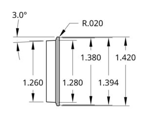
I have added all other dimensions to the wheel as shown in the image.
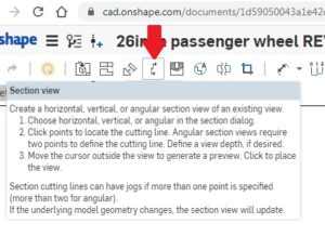
There are, however, dimensions that are hidden and are necessary for an accurate measurement of the part. To get these measurements into the drawing, we must do a section of the part. This effectively “cuts” the part at a location that you choose. The screen shot shows the icon that is needed to create the section view along with the help window.
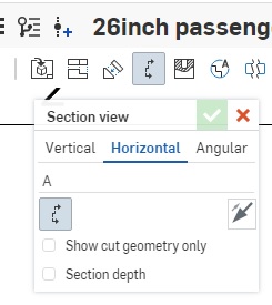
When you select the “Section view” icon, you will get a Section view dialog window that gives some options for using the section view tool. Using your mouse, in this case, select horizontal. Now you can move your mouse over to the location that you want to get a section cut of.
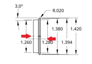
You will see in the drawing that several new drawing items have appeared. The arrow to the left shows the centerline, if applicable, of the item. The arrow on the right shows the section view cut line. Wherever you place this line is where you are going to get a sectioned view. I am going to place the section view line on the centerlines.
When I right click and move the mouse, at the location that I have selected a ghost of the sectional view appears. It can only go up or down from the drawing that the section view came from. (If we had selected vertical at the section view dialog box, it could have only gone to the right or left.) Right click at the location that you have selected and the screenshot shows what you should see:
The red arrow at the bottom of the image is the “callout” for the sectional view. In this case it is SECTION A – A. If you now look at the upper arrow you will find the A – A were the dashed line indicates the location of the center of the sectional view. We can now easily see and dimension what is “inside” of the wheel that we have just made. (Note: if you choose to try and move the sectional view, you will notice that you can! However, once you do that, the item where the sectional view came from will also move to keep everything centered.)
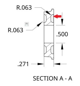
Now we can dimension those parts that are inside the wheel. In particular, I wanted to dimension the fillets that were created. The bottom image is the sectional view dimensioned as I would do it.
I was looking at the drawing and noticed a couple of lines shown by the red arrow in the bottom image. It took me a bit of research but these are the lines created by the outer fillet as if you where looking at the part as if it actually was cut in half. That solves that mystery.
![]()
I still want to add the face dimensions so I will go to the insert view icon. The picture below shows the icon, pointed to by the red arrow and the help dialog box.
I chose the left view orientation and moved my mouse down to the drawing area. A ghost image will again appear, as shown in the bottom screenshot. Click to place the image.
Do the same for a right image. You are now ready to dimension as you see fit.
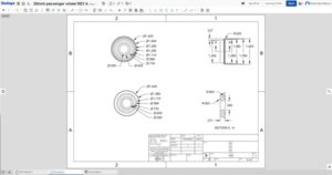
The finished drawing is shown in the top image. I went a little far with all the dimensions, but I have found that if I do not include them all, sooner or later I will want them.
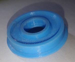
The finished part, printed out in PLA, is shown here. It is going to need a little more finishing here and there to clean it up sufficently.