Modeling Series Spaces To Places Spaces to Places V | Highway construction, part 5

Spaces to Places V | Highway construction, part 5

By Kent Johnson | May 13, 2024

Gerry shares his secrets to making superior sandpaper roads and streets

Email Newsletter

Get the newest photos, videos, stories, and more from Trains.com brands. Sign-up for email today!

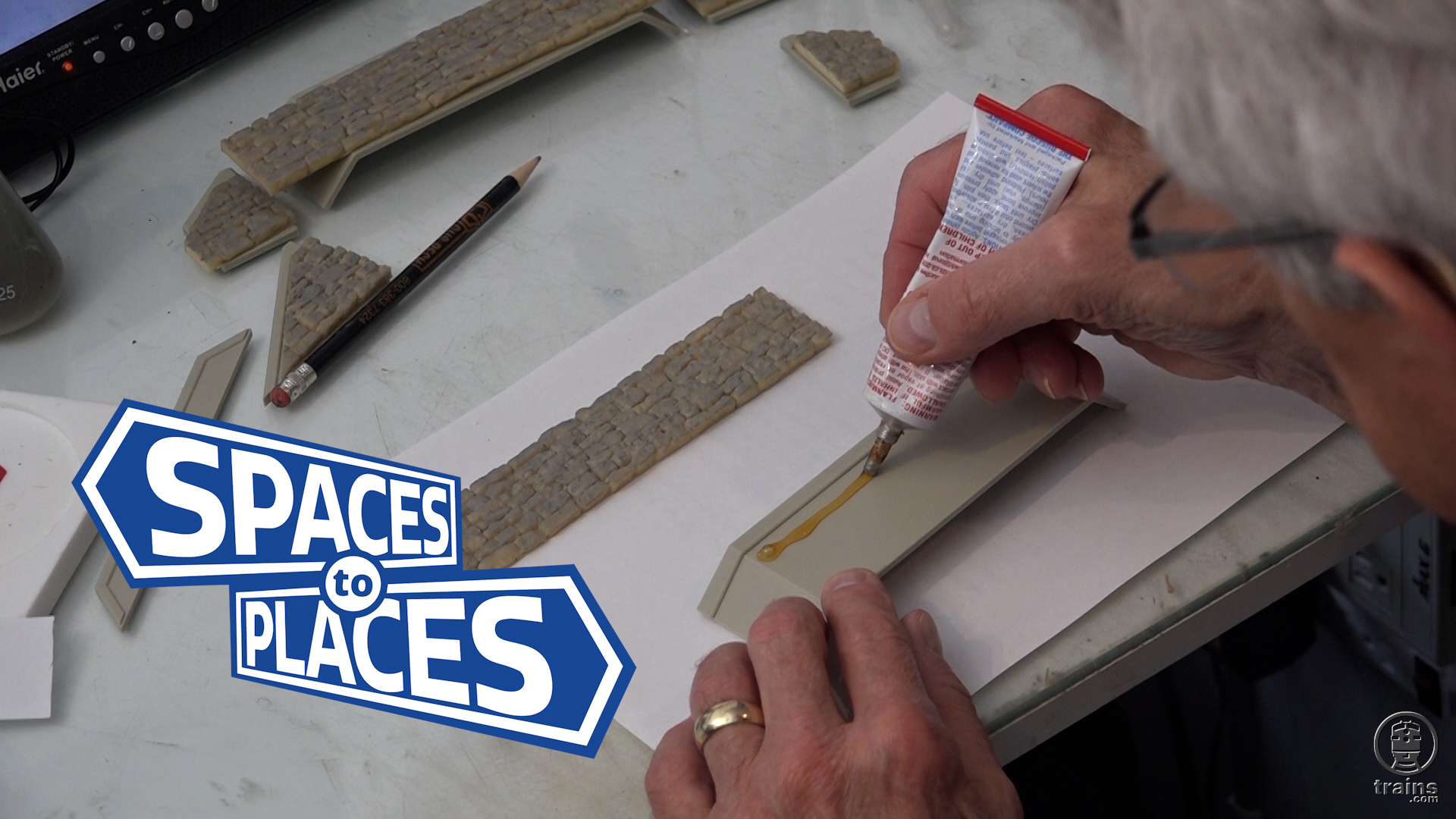
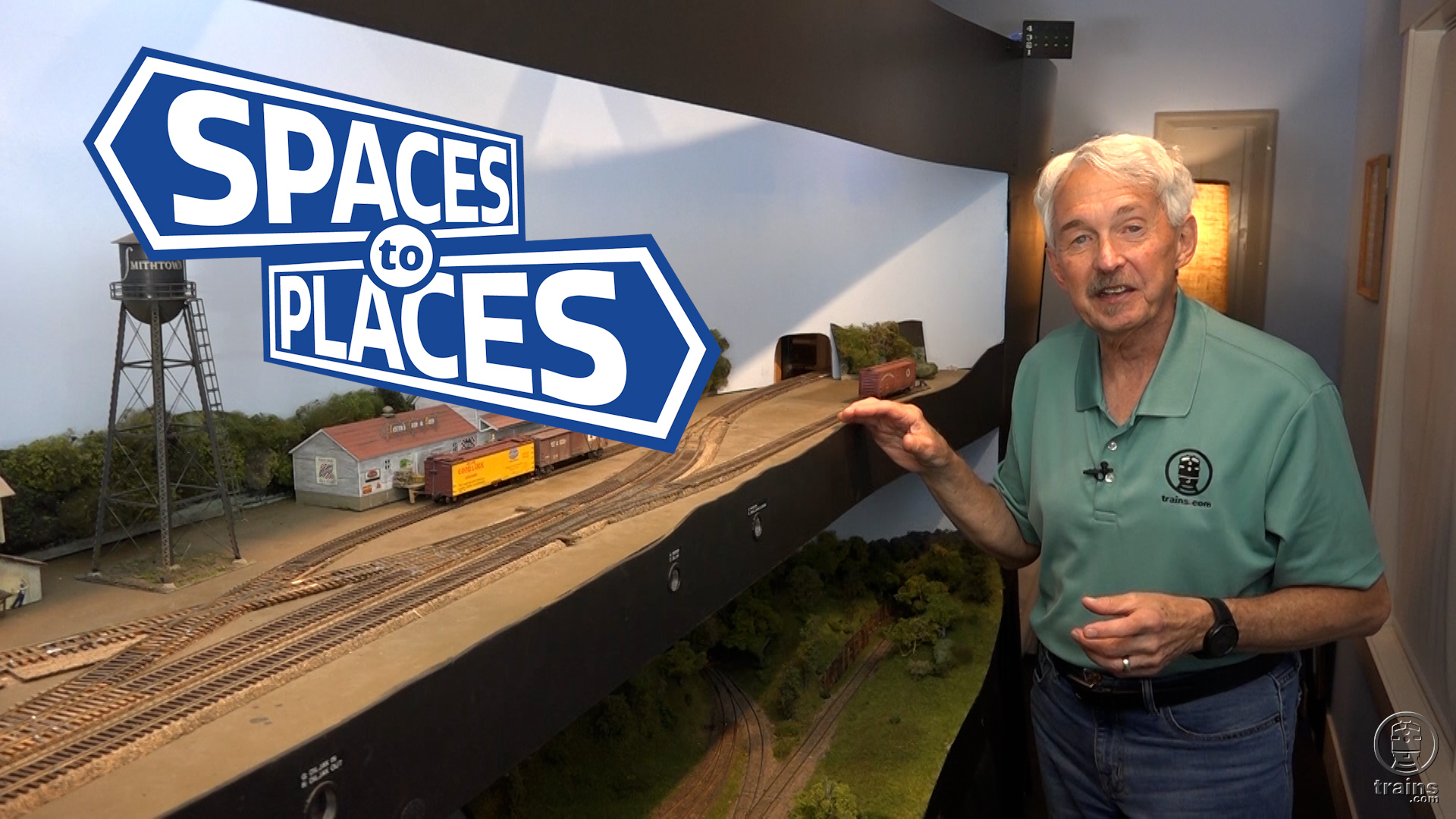
Host Gerry Leone sets his sights on highway construction for his HO scale Bona Vista model railroad. Catch up with his off-camera preliminary efforts, before following his technique for making authentic roads and streets using medium-grit sandpaper. As he notes, even more insights regarding this technique can be viewed in a prior Trains.com video series, Spaces to Places IV.

Want to see more of Gerry’s work on a classic, familiar format? Look for his Turning Spaces into Places Vol. 1: Rural Scenery DVD, available from the KalmbachHobbyStore.com!

5 thoughts on “Spaces to Places V | Highway construction, part 5

  1. FWIW, the dimensions for dashed lines on roadways, as established by the FHWA’s Manual on Uniform Traffic Control Devices, is 10′ stripe with 30′ gap – a 40′ pattern.

    Interesting information – this was changed with the 1972 MUTCD. Prior to that ’72 revision, the pattern was 15′ stripe/25′ gap – a 40′ pattern. The research behind the change in ’72 was 1) drivers could not distinguish between the [new] 10′ stripe vs the [previous] 15′ stripe and 2) there was a 33% reduction of paint for the dashed lines with no measurable negative impact to traffic safety.

    However, in using “selective compression” required for our modeling, ultimately, the best way is just “to make it look right.”

    Further, for the purists – couple of other significant changes in traffic control were part of the ’72 MUTCD –
    1) dashed lane lines went from white to yellow. Previously the dashed lines were white with [only] the No Passing Zone solid line being yellow. With the ’72 Manual, all centerline striping became yellow, bot dashed and solid, also denoting the left “border” between opposing traffic; traffic in the same direction was separated by white.
    2) both STOP and YIELD signs went from black letters on yellow backgrounds to white letters on red backgrounds.
    (Interesting side note ….. many kids toys which have any traffic signs STILL use yellow YIELD signs. When my daughter took Drivers Ed in ’93, she was the only one in her class who knew that YIELD signs were RED w/ white letters. Reckon being raised by a traffic engineer actually DID teach her some things ….. LOL ?? )
    ¯\_(ツ)_/¯

  2. Great idea of placing the second piece first! if you get the angle wrong on an end piece, the error only gets worse going further. Starting somewhere toward the middle cuts down on the size of any ‘erer’! ?

    Using a clean/non-glued piece between the two glue-covered pieces allows moving the glued covered pieces until they are aligned “purfectly”. Slowly slide that sheet from between the two glued pieces.

    If you don’t know any soft-shoe steps, get some tap dance shoes! Just be careful to not knock over that can of cement! ?

    1. Jim — on rare occasions I get a stroke of brilliance, and I guess you witnessed it here with the “second sheet first” thing. But I think I’ll pass on the tap shoes…!

  3. What is and where do you get “Pay Lite”, Gerry? Why is it better than Polyethylene for your road base?.

    1. Mark — The stuff is Palight. It’s the same thickness as .080” styrene, but it’s made of two sheets of extremely thin PVC, with a very thin layer of foam between them. It’s not necessarily better than styrene and you can only glue it to itself using PVC cement (like for putting PVC pipes together). But it was the only thing the printer had in stock and I decided to give it a try. I like it, but I don’t know that I’d go out of my way to buy it again if styrene is available.

You must login to submit a comment