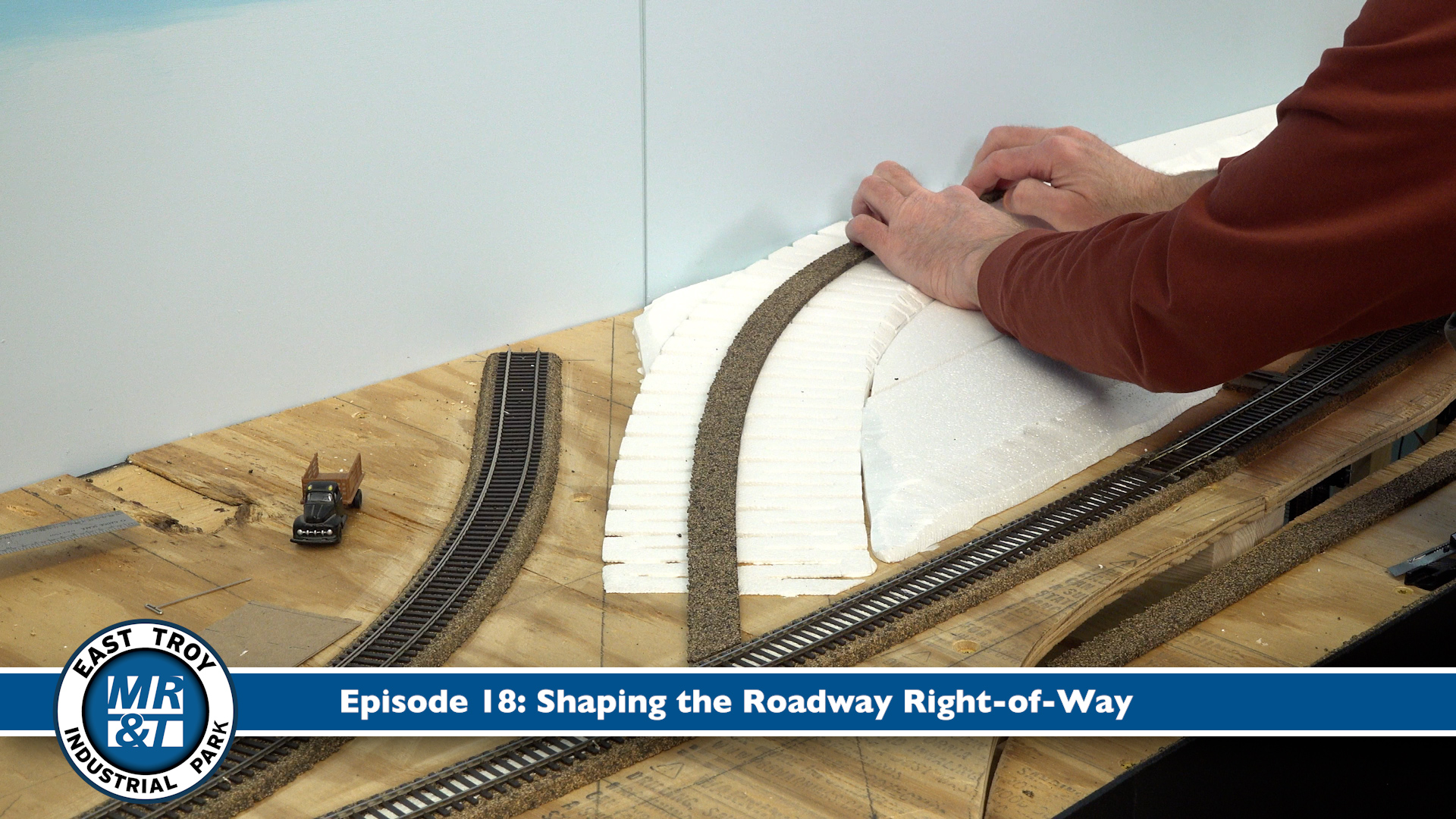
Hosts David Popp and Bryson Sleppy take a swing at the curves! Specifically, the process required to install sections of flexible track around the arching mainline, sidings, and spurs on the HO scale (1:87.1) East Troy Industrial Park project layout. Follow their insightful instructions for making free-flowing, yet reliable trackwork on your next model railroad!
Be sure to keep up with the construction progress by linking into the Trains.com Workshop Webcam (available 24/7), and the full series of helpful, instructional videos rolling out every month until the effort concludes. Even then, the fun will continue in frequent Trains.com articles/updates and Model Railroader print features, beginning with the January 2026 issue. You won’t want to miss the Expert Tips and Techniques the crew will share with you along the way, as they have a bit of fun bringing the ETIP into fruition!
Great shot of your thumb when soldering at first LOL!
As you laid in your curved track, is there a concenr for the alignment of both track in the radius and do you use a guide to ensure it will not bind or cause a derail? As mentioned above by Roger, you did adjust the cork roadbed?
Alas, I also noted your removal of glasses for the close in work – the bane of our aging existence!!
Great video for techniques on soldering too.
Do you have any tips or special techniques for connecting curved track that crosses moveable layout sections?
Hi Kerry, when you have to have track over curved sections, you can make your own rigid curved splice by soldering PC ties to both ends of it. With one or two ties soldered at each end, they should keep it the curve from losing its shape.
First, lay flextrack all the way through the curve between the layout sections normally. Then carefully remove enough of the plastic ties on either side of the section joint where you want to add the PC ties. Be sure to leave room for rail joiners; they will need to be able to slide all the way back on one end of the splice to be able to remove it.
Once you have the PC ties in the proper position, solder them to the rails on both sides of the section you intend to cut. When the solder has cooled, cut the rails between the two sets of PC ties on both ends of the section joint and remove the new curved splice piece.
After cleaning up the solder residue, you should be able to replace or remove the splice section by sliding the rail joiners back on one end of it. Good luck with the project!
Thanks for the tip on how to lay flex track on curves. I never thought about making sure the open ties were on the inside of curve. Great informative videos.
Good comment. I would not have thought about that either. Timely information for me!
When working on curves bend the rails in and tack them down with spikes glue can not hold curves because it acts like a spring. Also flex track can kink if bent so solder the sections on the straights and install gaps or it will come out of alinement later due to humidity.
As I recall, when the roadbed for this curve was laid down, you adjusted the high end slightly away from the CN main to provide room for enough space for a realistic scenery treatment between the two, and this allowed space at the lower end for an easement between the curve and straight. Have you allowed for easements on ALL curves on the layout, including spurs, and, if so, how was this done? Easements on tighter radius curves are more critical than broader curves to obtain smooth car and loco movement when traversed.
Hello Roger, I did not purposefully draw easements onto the layout when setting the track centers. The cork and later the flex track will form natural easements on their own. (You actually have to work really hard to prevent them from doing this if you want a true radius curve off the tangent track.) If we were laying track for a main line that would run passenger trains, auto racks, or other longer cars like that, I would have drawn them in when we laid out the centers. 18″ is usually a good rule of thumb for an easement into 28″ to 30″ curves, which is what we have here.
Adjusting the curve inboard a bit to provide room between the CN main line did change the radius some, but as this is a dead-end fiddle track, the change in curvature isn’t significant enough to cause any trouble with longer cars.
Great question, though and something I should have addressed in the video. Thanks!