– Richard K. Hoffman, Bowling Green, Ky.
A With the introduction of electrical track circuits in the late 19th century, fail-safe operation entailed introducing electrical energy via connections to the rails at one end of a track circuit and an electro-mechanical device called a relay connected to the rails at the other. Track circuit boundaries were established using insulated joints to prevent the electrical energy from one circuit interfering with its neighbor. If conditions through the “steady energy” track circuit were safe for train operations (no train occupying the circuit, no broken rail, no hand-throw switch left open, etc.), then the relay would energize, indicating to the signal system the track circuit was safe for train movement.
As train speeds and tonnages increased, trains required longer distances to come to a stop. Wayside signals were installed at locations determined by the engineering department to alert train crews to begin to slow and come to a stop in a controlled, safe manner. The distance between signals is usually referred to as a “block” and includes one or more track circuits, depending on the length limitations of the steady energy track circuits and the physical characteristics of the track structure itself.
Open-wire pole lines were used to enable a signal at one location to determine how many blocks in advance were safe for train movement. Changes in track circuits at one location would cause one or more relays to de-energize, which then would change the energy being sent out over the pole line to adjoining locations. This would cause relays at the adjacent locations to change state, which then further changed the energy sent to neighboring relays via the pole line, and so on.
Ultimately, railroads looked for ways to dispose of the high maintenance costs associated with open-wire pole lines (especially after an ice storm). One solution was to bury the pole line in wayside cable along the right-of-way. Another was to use “coded” track relays, which changed state at a pre-defined rate. Track circuit lengths could be lengthened because this pulsating energy, or “code rate,” traveled farther along a given section of track than steady energy would. More information could be sent between signal locations by using several different code rates. However, “mechanically coded” track circuits required more relays at each location than steady-energy circuits, especially if the track was signaled for train movement in both directions. And the code relays themselves would drift in and out of tolerance over time, as the mechanical components inside wore out much faster than their steady-energy counterparts.
The electronically coded track circuit was introduced in the 1970s as an alternative to open-wire pole lines or mechanical code relays. The electrical code rate was generated by solid-state components and usually controlled by some type of microprocessor system. Some systems (including Electro Code) vary the delay time between two identical code pulses. The different delay times, or “codes,” were decoded at the adjacent signal locations, indicating track circuit and signal aspect information. Each location would update its own signal aspects, and then send different codes to its neighboring signal location. Only one “code box” was required at each location because it could transmit and receive codes, whereas any given relay could only transmit or receive code depending on its construction. The code boxes are connected to each end of a given track circuit with their polarities staggered so they can receive and transmit simultaneously (each taking turns being the “feed” end or the “relay” end of the track circuit). A code box could be configured to accommodate the aspects and operational requirements of each individual railroad or transit property by changing the programming inside the microprocessor.
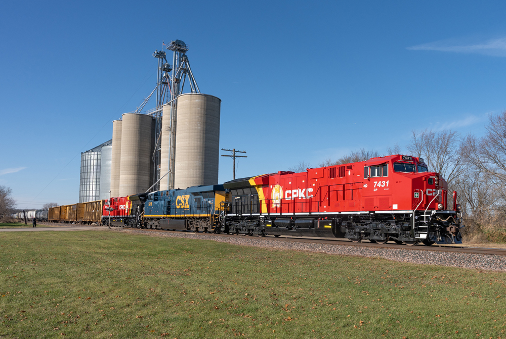
From the perspective of a wayside railfan, it’s difficult to tell whether a given location uses steady-energy track circuits, mechanically coded track circuits, or electronically coded track circuits. Each type may be found in service today with color light signals and searchlight signals. To have reworked the elderly Monon semaphores with Electro Code would have required more engineering and construction effort than replacing the entire system. Parts for semaphores are hard to come by these days, after all.
In the interest of disclosure, I began my Class I career on CSX’s Monon Sub on a “pole line elimination” signal gang working between Munster and Lafayette, Ind. While all the signals we retired were searchlights, they were coming out for the same reasons the semaphores are coming down: It was more cost-effective to replace the entire system with Electro Code and color light signals.
Color light signals lack the moving parts searchlight and semaphore signals have, eliminating a number of Federal Railroad Administration-mandated periodic tests for signal maintainers to conduct at each location.
– M.J. Engels, signal design principal, ESCORRT LLC
Q When diesel-electric locomotives were beginning to replace steam, railroads sometimes used steam-diesel doubleheaders to pull trains. The diesel was placed ahead of the steam engine. What was the advantage of that order?
-Ernest F. Hubacker, Jamestown, N.D.
A In the days when steam coexisted with diesels, railroads that mixed them on the head ends of trains often specified that the diesel should lead and the steam locomotive should be next to the train. They felt that smoke and cinders from a leading steam engine would be bad for the air intake filters of the diesels, and maybe bad for the then-fancy diesel paint jobs. In winters in the Northern areas, the steam engine was often next to the train because of its greater capacity for supplying steam for train heating, especially before steam generators on diesels gained in reliability.
On short stretches such as helper districts over mountains, the steam locomotive was often coupled ahead of the diesels for operating convenience; for example, there are many photos of steam locomotives (often freight engines) leading Santa Fe passenger diesels in the mountains. It would be inefficient to uncouple the diesels at the bottom of the grade, cut in the helper, then reverse the process at the top (to say nothing of breaking the steam and signal connections, which would have to be furnished on the helpers).
– Ed King
Q We saw a Norfolk Southern research vehicle at the East End Shops in Roanoke, Va. Any idea what this vehicle is and what it is used for?
-Mark Mashburn, Hickory, N.C., and Brian Stevens, Roanoke, Va.
A NS 34 is a former locomotive slug used for testing track geometry. The vehicle is ballasted to elicit a response from the track similar to that of a loaded car or locomotive. An inertial package with a laser/camera system is mounted on one of the trucks to measure irregularities in track geometry and to acquire data on rail wear. A high-resolution machine vision system also acquires data on rail surface and crosstie/fastener condition. The cab was added to house the computers, control equipment, and a GPS system.
NS 34 also contains a generator that powers its on-board systems, as well as the converted coach, NS 33, to which NS 34 is mated. NS 33 has monitors that display the data acquired by the sensors and measuring devices on NS 34, and NS 33 also was recently equipped with a rotating laser to measure and evaluate clearances, ballast profiles, and track centers. NS 33 has a galley and theater seating looking toward a large back picture window for track, bridge, and signal supervisors who ride in the car.
NS is outfitting a second track geometry consist (coach NS 36 and former NS locomotive 38) that will be configured similarly to NS 33/34. NS expects the new consist to be in service by the end of first-quarter 2009.
Norfolk Southern’s Research and Tests Department operate NS 33 and 34 to test track for the engineering department. The data the cars produce pinpoint track defects (which are quickly repaired) and are important for preventing accidents, and planning routine and system maintenance work. The track parameters it measures include gauge (the distance between the rails), curvature, cross level (the difference in height between rails in curves), cant (the outward flexing of the rails), and other characteristics critical to safe operations. The system also measures the amount of steel worn off the top- and gauge-faces of the rails.
NS 34 was originally Norfolk & Western SD35 No. 1530, which General Motors built in 1965. The East End Locomotive Shops rebuilt it in 1977 as a road slug, model RP-E6, and renumbered it 9921, then 9951. NS put the slug into storage in 1993, then rebuilt it in 1998 to carry the track measuring system for Research and Tests. NS 33, built by Pullman Standard in 1950, began service as a Union Pacific coach. In 1971, UP sold it to the Alaska Railroad, which renumbered it 5441. Alaska Railroad retired 5441 in 1987 and sold it to St. Louis Car. NS bought the car in 1994, and rebuilt it at Roanoke’s East End Passenger Car Shop for the Research and Tests Department. NS put the car (now 33) in service on Aug. 9, 1999.
NS 33 and 34 travel the system several times a year and test more than 18,000 miles of heavy-duty main line annually. The cars are operated by two Research and Tests Department engineers and staffed by Maintenance of Way & Structures managers responsible for track, bridge, and signal maintenance.
– Russ McDaniel, director – process improvement, Research and Tests, Norfolk Southern
Q I recently saw a string of CSX hoppers in maintenance-of-way colors, each with arrays of solar panels on the ends and sides. What are these for?
– Jeff Monner, Vienna, Va.
A The bottom-dump mechanism on CSX ballast cars is battery-operated. The solar panels keep these batteries charged as CSX installs ballast. It’s an example of the company’s ongoing attempts to save energy.
– Eric Powell