


Track wiring your model railroad layout can be daunting, especially for beginners to the hobby. In order to help those looking to start, here’s a review of the bare-bones basics of wiring your layout that will help you get your trains up and running as quickly as possible.
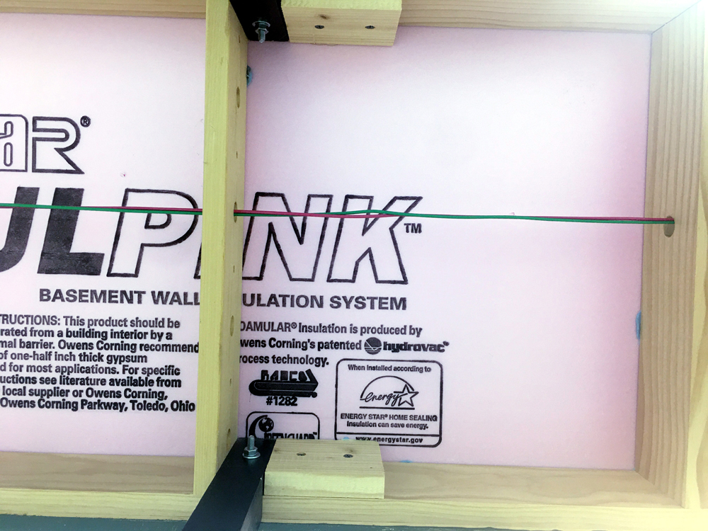
Run the wire bus roughly beneath the area where you have the track (beneath the center yard track, beneath the main line, etc.) The bus will consist of two 14-gauge stranded wires, one red and one green. When you get to the end of the bus run, secure the ends so they can’t accidentally touch. (I’m often asked if the bus should be one continuous loop without ends. The answer is no.)
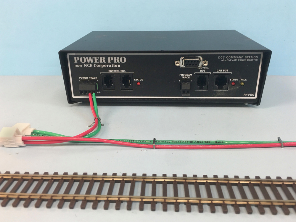
Next, we want to connect the booster to the bus. Although it doesn’t have to be exact to the inch, you want the booster to be roughly in the middle of the bus wire run, not located at one end or the other. Take two 14AWG wires and, using the designated taps on the booster, connect them to the bus.
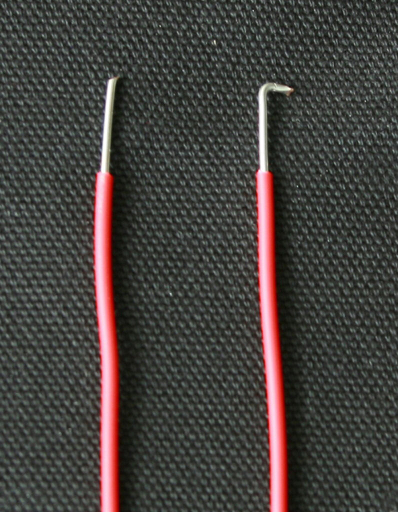
The next step is to connect the track to the bus. This is done using wires called feeders. I use 18AWG solid wire spaced roughly every 6 feet or so. Each connection location will consist of a pair of two feeder wires, one on each rail. First we need to prep the feeder wires. Strip about a half inch of insulation off of the end of the wire and then make a ⅛” “L” at the end. Putting a slight bend at the end will make it easier to nestle into the side of the rail web.
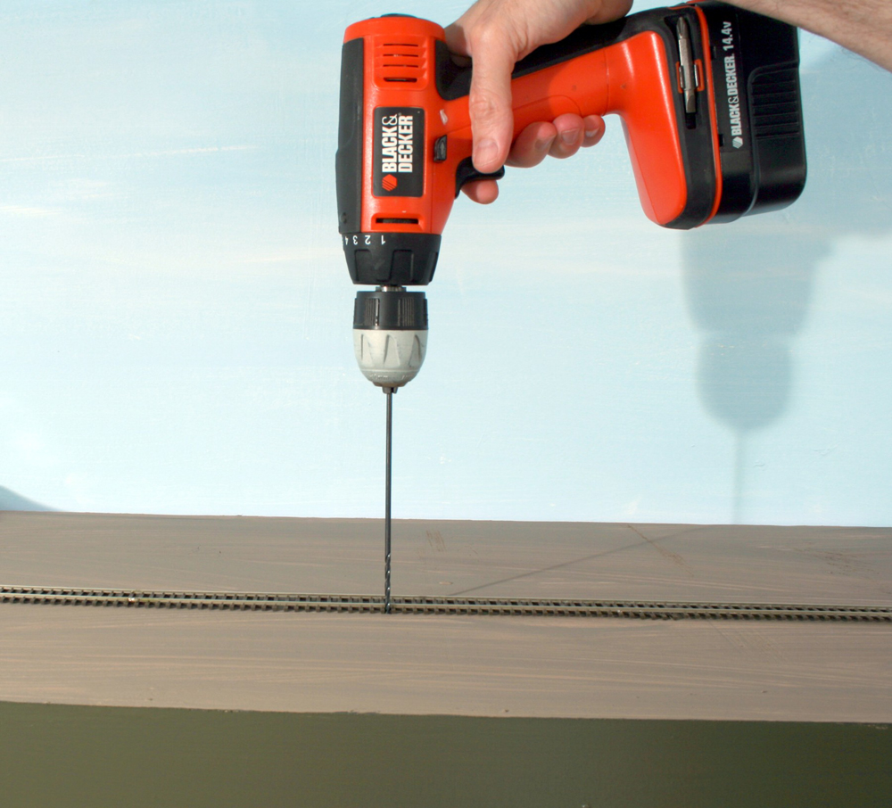
When googling sources for the 18AWG wire, the technical term is “hook up” wire. When cutting the feeders to length, make sure they are long enough to reach from the track to the bus beneath the layout. Make them a few inches too long for good measure. Drill a hole for the feeder wires next to the track and through the roadbed. I use 3⁄32″ bits. Longer drill bits are called “aircraft bits” and reduce the chance of the drill slamming through suddenly and damaging the track. Slip the feeder wire through the hole.
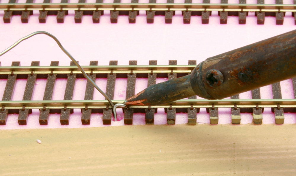
Next, you want to solder the feeder to the side of the rail. Put a drop of flux at the connection, firmly push the soldering iron at the connection point, and then touch the solder to the area. In a matter of seconds it will flow into the joint. Solder a pair of feeder wires to your rail every 6 feet or so.
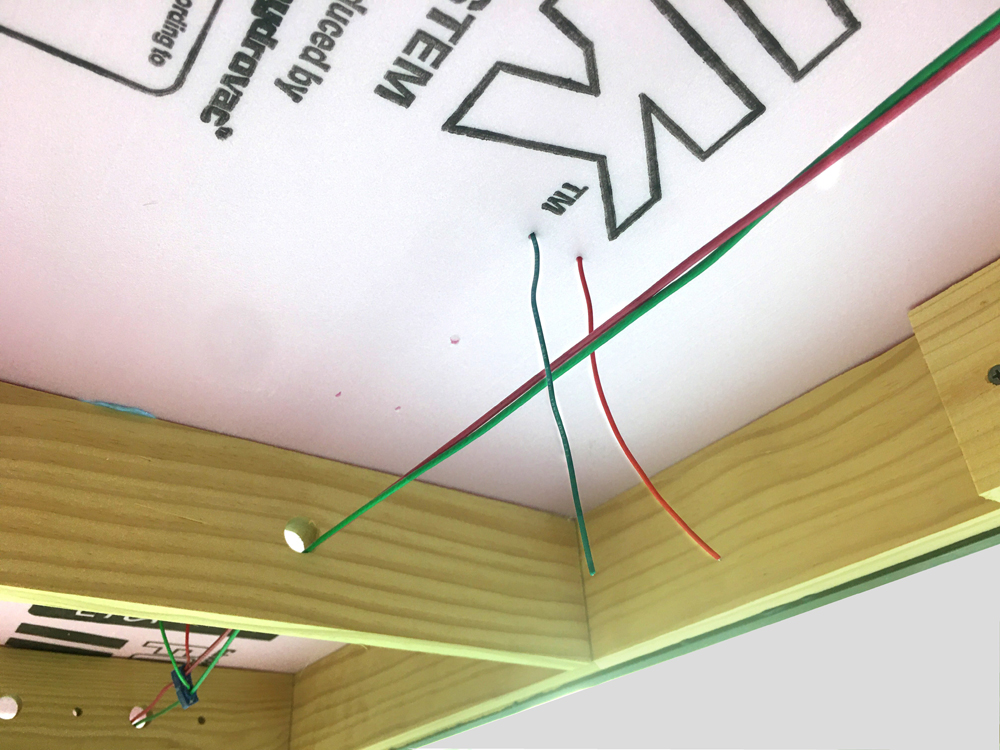
Don’t connect them to the bus just yet; for now, let them dangle. Try to go slow and double check your work to make sure you maintain consistent polarity with all red feeds on one rail and green feeds on the other rail. If you connect even one feeder wrong, you’ll get a short.
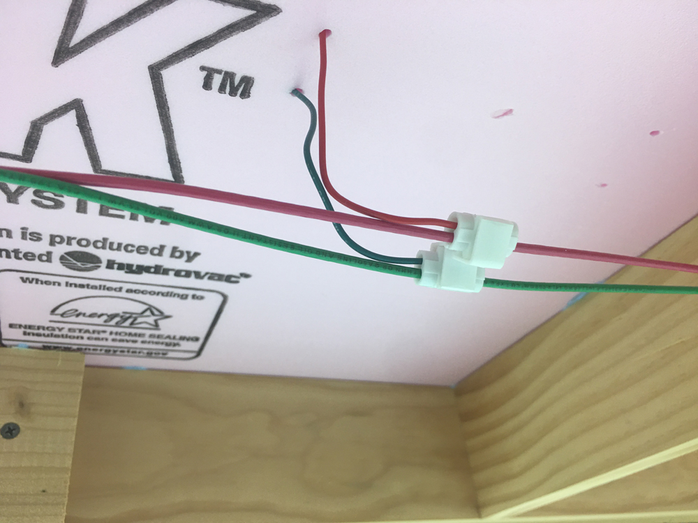
At this point we have the bus in place and the feeders soldered to the track but not connected. Now comes the last, and most fun step: bringing your model railroad layout to life so you can run trains! This is done by connecting the feeder pairs, one set at a time, to the bus. Make the connection using tap connectors (also known as “suitcase connectors”).
Turn the layout power (meaning your DCC system or power pack) on. Place a locomotive on the track. Connect one set of feeders to the rail. Why only one? Because if you make a wiring error and get a short, you’ll know the error was at the last connection. If you connect all of the feeders at once, power on, and have a short, then you don’t know which connection is at fault. I’m speaking from experience!
Most DCC systems have audible alarms and lights on the booster that signal a short. As I connect the feeders, I keep my ears open. Is the DCC system’s short-circuit alarm silent? Does the headlight on the locomotive turn on? Will the locomotive run? Great, you’re in business! Move on to the next pair of feeders and connect them to the bus. Continue making the connections and listening for the short-circuit alarm until you’re done. That’s it, you’ve now conquered model railroad layout track wiring for beginners!

Hi Frank,
Those are Insulation Displacement Connectors (IDCs), suitcase connectors, or Scotchlok connectors. Search any of those names online and you’ll find sources for them. Occasionally, you’ll find them at home improvement centers or well-stocked hardware stores, but to get the quantities a medium to large size layout can swallow up, it might make more sense to buy them online.
Be sure to choose connectors that will work with the wire gauges you’re using for feeders and bus wires. You may need to use intermediately sized connectors if there’s a large difference between feeder gauge and bus wire gauge.
Where do you purchase the nice connectors that join the track feed to the main distribution wire? What are they called? I’ve not seen these before. Thanks!