


There is probably no other aspect of our hobby that creates more anxiety and confusion for newcomers than wiring. When you’re starting at absolute ground zero on the learning curve it can be daunting at times. However, at the most basic level, what we’re trying to do is get electricity from a power source to the rails so our trains will run.
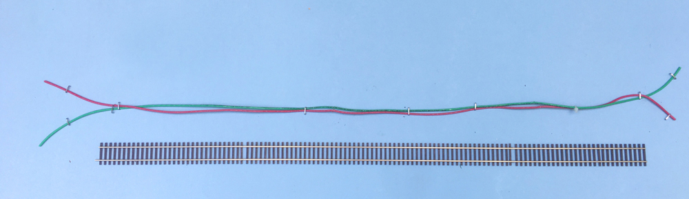
Power comes out of your DCC system through the “booster” via two wires. Just as water runs down your neighborhood street via a main, power is distributed to your layout via two thick wires called a “power bus”. Staying with the water analogy, just as service lines leave the water main on the street to go to individual houses, smaller wires called “feeders” tap off of the bus and connect to the rails.
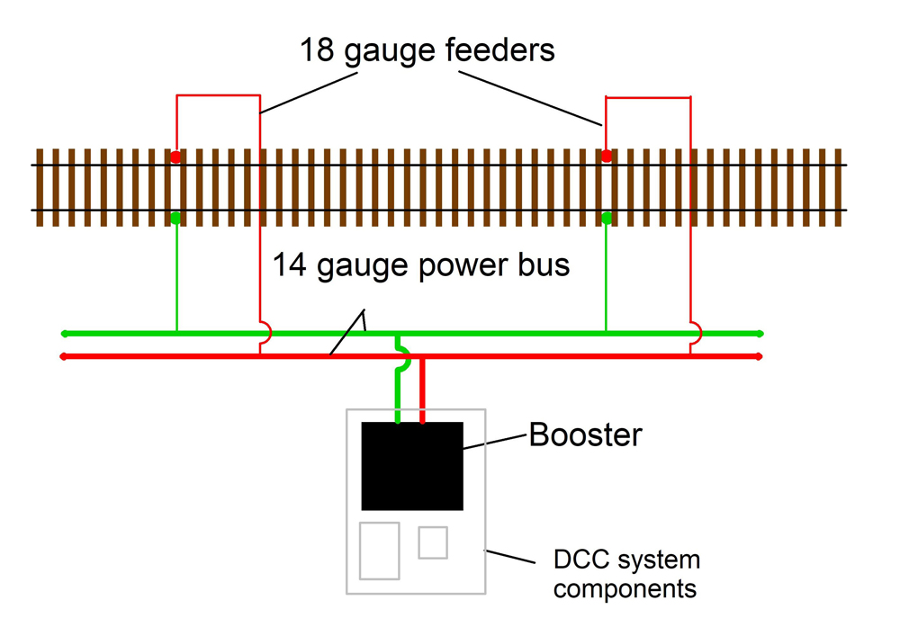
The path that power takes in getting to your locomotive starts at the booster, goes to the bus, and then travels through feeders to get to the track. You are creating a simple route that connects the power exiting the booster to the track. (Note: I’m assuming most people use DCC. If you’re using a DC power pack then power comes out of the two “variable DC” screw terminals.)
Since the power will be traveling through wires, let’s first cover a few basics. Wire size is measured by “gauge.” The abbreviation AWG stands for American Wire Gauge.
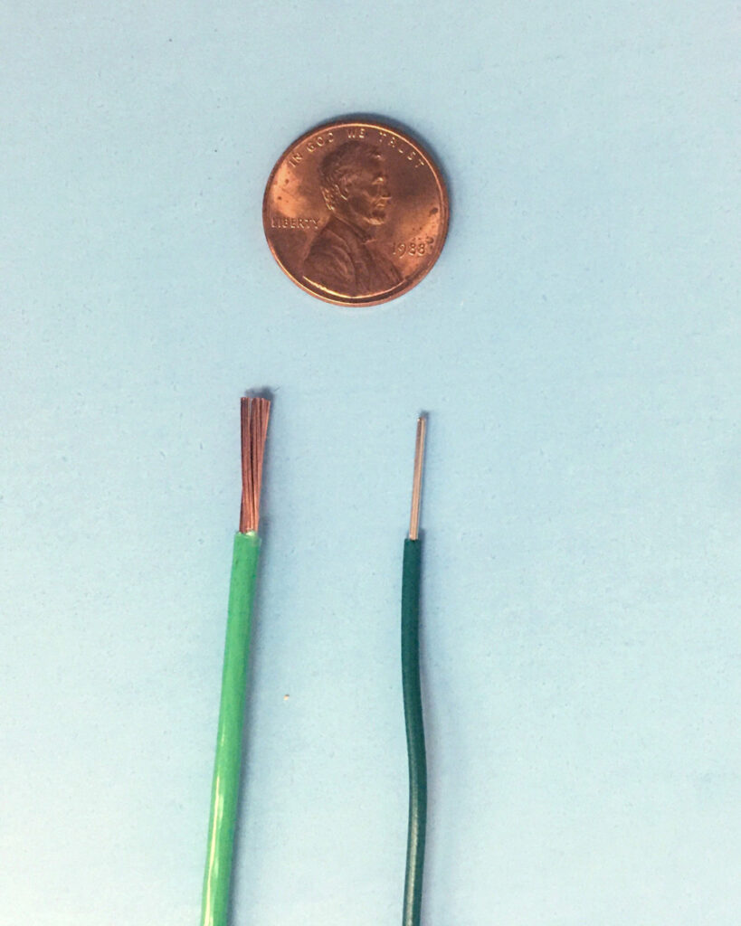
The smaller the number, the larger the wire. For example, as seen in the image above, the 14AWG wire on the left is larger than the 18AWG wire on the right. If you use wire that’s too small, you’ll run into problems like overheating. There is no harm in going too large, but working with bigger wires can be more cumbersome.
For an HO scale, 20 x 20-foot, half-basement layout or smaller, I suggest 14AWG stranded wire for the main bus and 18AWG solid wire for the feeders. Wire comes in two forms, stranded and solid. Whether you use solid or stranded doesn’t matter that much. Stranded is more flexible and easier to use in situations where you have long runs, such as the main power bus.
Personally, I find solid wire easier to work with when for soldering and prefer it for the feeders, which you will be soldering to the sides of the rails. I use the same standards for N scale, as well. Even if you could get away with slightly smaller wire, it’s harder to work with if you have aging eyes.
Color coding your wires while working is vital to keeping things straight with respect to correct polarity. It’s really easy to get turned around and accidentally reverse one set of feeders, causing a short. I prefer to use red and green wires, but you can use any color as long as you’re consistent.
With this introduction information under your belt, you’re ready to start with the actual wiring of your layout! Check out this article on beginning the process to get your locomotives up and running.
Learn more
Canadian Canyons: Installing bus wiring


The heading and text should have referred to DCC power. The description is unnecessarily complex for straight DC supply.