I like to use signs in my railroad to provide a more prototypical appearance. This includes the use of humorous signs like those I have seen in my travels. In this example, we will be using a free modeler called openSCAD to model the sign. That way you can model your own signs to meet the size and wording requirements that you have.
openSCAD
I have discussed how to download the openSCAD in a previous article, so I’ll not cover it again. If you cannot find the article, just Google “openSCAD” — they have good instructions for downloading, executing, and using the program.
I generally model in “SolidWorks,” an expensive, professional designer modeling program. For the hobbyist, this is just too expensive and way too complicated to use. My next favorite modeling tool is “openSCAD,” which I often use with great success. I like it because it is more like a computer language. I can set up variables to make the part and, if I want something different, I just change the variable.
For example, if I want a sign modeled in 1:20.32 scale, I create a variable called “scale” and set it equal to 20.32. But what if I want to scale it to 1:24? I simply change the “scale” variable to 24 and recompile. It is that easy. The same can be said for the length, height, and the wording.
I make signs for my buildings, population signs, and railroad signs. I enjoy using unusual names of towns and lakes that I have encountered in my travels.
So let’s make some signs. In this example, I am going to make a sign for my hardware store. The name comes from Needmore, Indiana, a town just north of Bedford, Indiana. I thought “Needmore Hardware” would be appropriate.
OpenSCAD Program
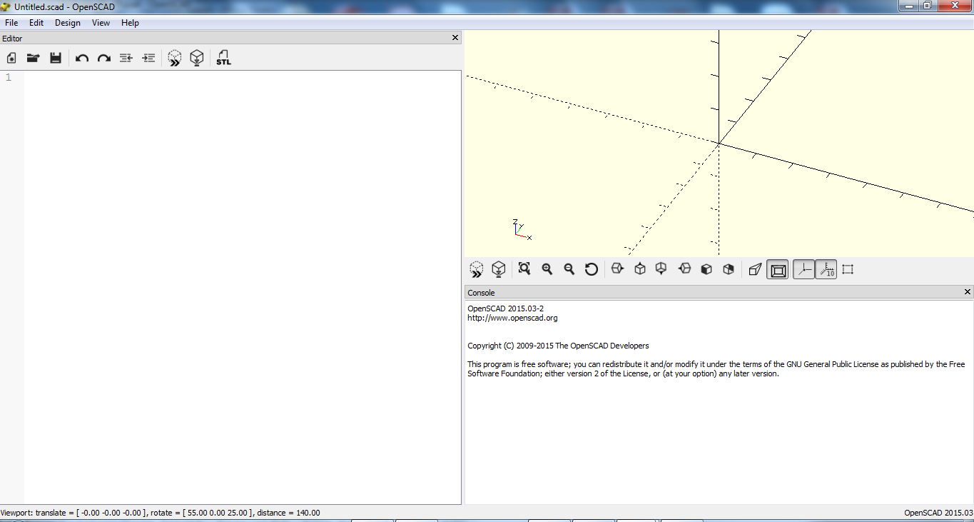
Photo 1 is a screenshot of the openSCAD workspace.
On the left you will see the Editor window, where we will be entering the text; at the upper right is the display window, which shows the object we are making; and at the bottom right is the Console, which is where the program is going to tell us what is going on and the results of the program.
Variables
The first thing we are going to describe are the variables that we will use.
The first variable is mm_inch. Since openSCAD does everything in millimeters and I am working in inches, we need the conversion factor mm_inch to get everything into inches.
Next is the scale variable. As you can see below, I am using the scale 20.32. If you want scale 24, use 24 for the scale variable.
I like a raised border around the sign of 0.05”. I describe that with the border variable and use the mm_inch variable to convert 0.05” to millimeters.
Next, I am going to describe the font to be used on the sign, as well as the letter size and letter height. OpenSCAD includes these fonts: “Liberation Mono, Liberation Sans, Sans Narrow, and Liberation Serif.” You can install and use additional fonts but that is beyond what I am going to talk about here. I used the Bold style but you can also use Italic, Bold Italic, or nothing at all.
For a regular font, you would use: “font = “Liberation Sans”; The letter_size variable describes the height of the letters above the text baseline. I wanted 0.26” and, again, multiplied it by the variable mm_inch to get it to the units used by openSCAD.
The variable letter_height describes how high the letters will be above the plane on which they are placed. (Note on the fonts: You can use different fonts if you are willing to do some extra work for it. I refer you to https://en.wikibooks.org/wiki/OpenSCAD_User_Manual/Text for additional information on how to use text and change the fonts.)
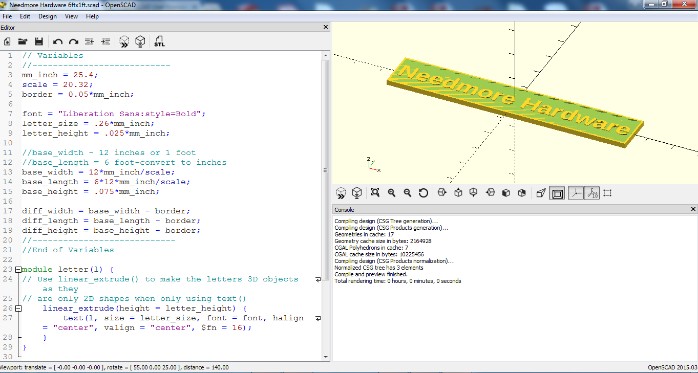
// Variables
//—————————
mm_inch = 25.4;
scale = 20.32;
border = 0.05*mm_inch;
font = “Liberation Sans:style=Bold”;
letter_size = .26*mm_inch;
letter_height = .025*mm_inch;
//base_width – 12 inches or 1 foot
//base_length = 6 foot-convert to inches
base_width = 12*mm_inch/scale;
base_length = 6*12*mm_inch/scale;
base_height = .075*mm_inch;
diff_width = base_width – border;
diff_length = base_length – border;
diff_height = base_height – border;
//—————————-
//End of Variables
The prototype dimensions of the sign are 6 feet long by 1 foot high. Thus, the variable base_width equals 12 inches x mm_inch to make it in dimensions understood by openSCAD and divided by the scale.
So, the variable base_width equals 6 feet x 12 inches/foot x mm_inch variable ÷ by the scale.
The next three variables are diff_width, diff_length, and diff_height. These variables will be used to “cut-out” an area in the sign to create the borders around the sign.
Module
If you are somewhat familiar with programming, there are function calls that allow the code to be used over and over again. A module in openSCAD is like a function except it will not return a value. The module letter(1) takes two-dimensional text and makes it three dimensional. TThere are plenty of parameters that are used but I will not go into them, since everything is already defined by a variable. We will call this module later on to create three-dimensional text for our sign.
module letter(l) {
// Use linear_extrude() to make the letters 3D objects as they
// are only 2D shapes when only using text()
linear_extrude(height = letter_height) {
text(l, size = letter_size, font = font, halign = “center”, valign = “center”, $fn = 16);
}
}
Program
The program is very simple: create two cubes, then take the difference of the two, leaving the base of our sign.
difference() {
cube(size=[base_length, base_width, base_height], center = true);
translate([0, 0, border/2])
cube(size=[diff_length, diff_width, diff_height], center = true);
}
translate([0, 0, border/2]) letter(“Needmore Hardware”);
Let’s break this down. The operator module difference() takes the difference of two or more objects created between the curly brackets.
In this case we have created two cubes that make up the base of the sign. Notice that one is based on the base_xxx variables (this makes up the total size of the sign) and the other on the diff_xxx variables that make up the cube that we want to cut out of the base.
But before we take out the difference cube we must translate (move) the cube up slightly so we keep the base of the sign where we are going to put the text.
The last step is creating the text. We are going to translate the lettering up slightly from the origin to the plane created by the difference between the two cubes. We use the module called letter(“Needmore Hardware”) to set the text. Want a different text on the sign? If so, just change it here.
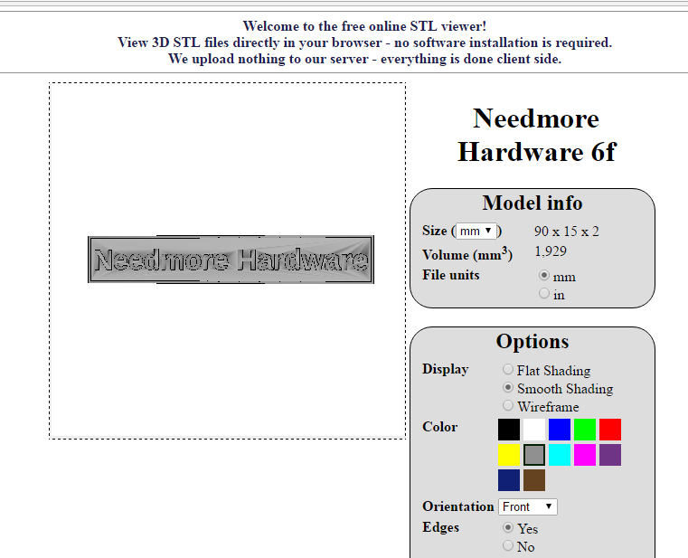
Preview
I always preview my stl models using a web-based application, like www.viewstl.com
Printing
You can take the .stl file to the www.hubs.com and find a printer near you, print your own if you own a printer, or try your local library to see if they have one that you can use.
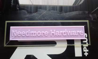
Photo 6 shows the 1:20.32-scaled sign on the printer bed.
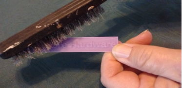
We can see that there is some plastic between the letters that should not be there. This is easy to take care of: use a wire brush to take out the plastic strings (photo 7).
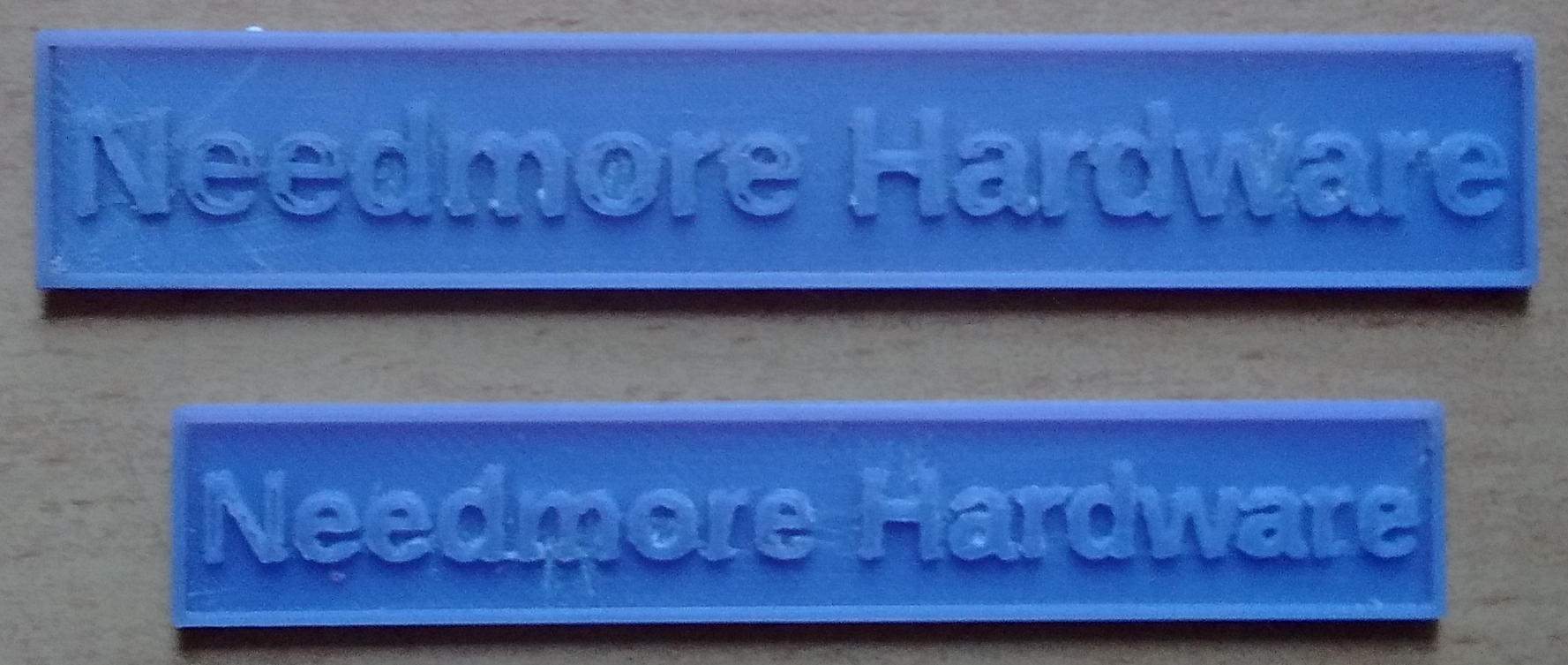
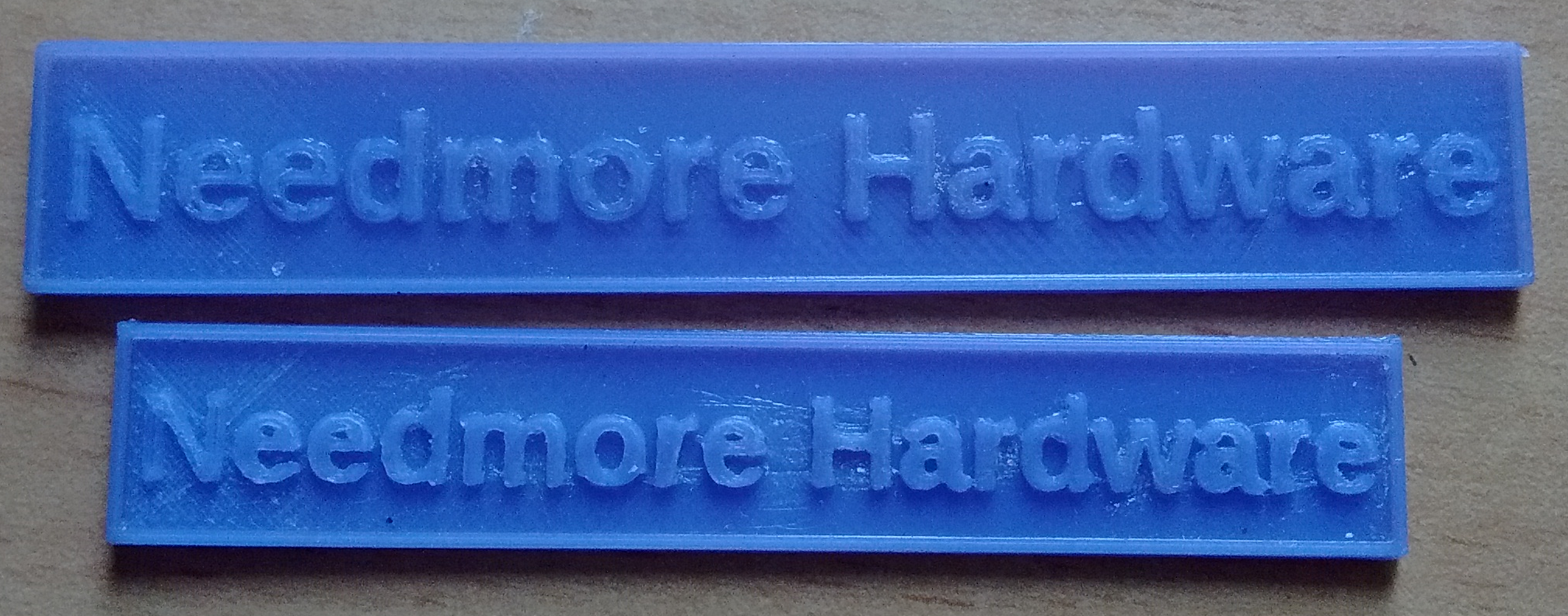
I also printed out a 1:24-scale sign. I changed the scale variable to 24 and also changed the variable letter_size to make sure the text fit into the frame of the sign. Here are the two signs in photo 8.
After spending some time in an Acteone vapor bath, they are cleaned up as shown in photo 9.
Painting
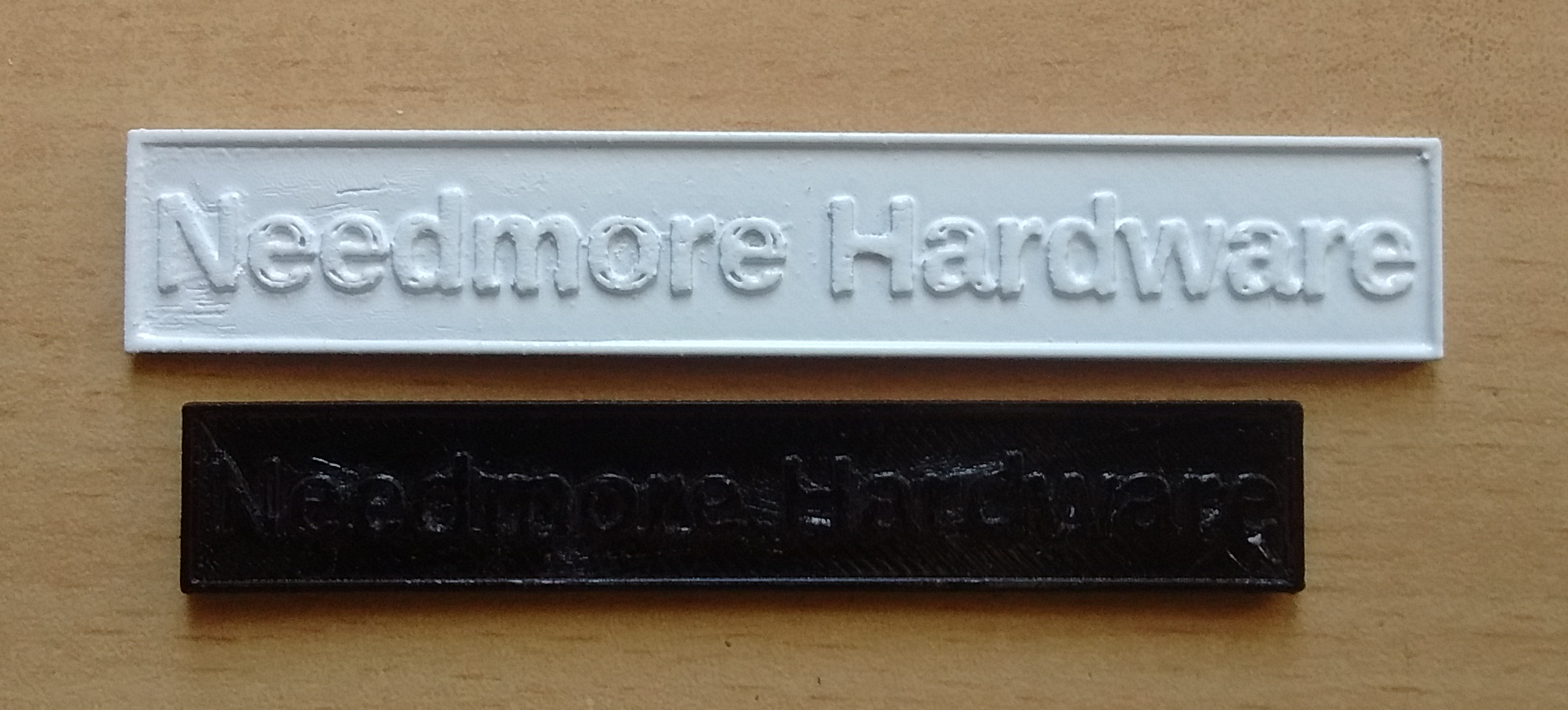
I printed them out using ABS filament, which is what I recommend for anything that is going to sit outside. It is UV resistant and will not melt when it rains, as PLA filament does. I am going to paint my signs with a spray enamel but, before I do that, I hot-glue them to sticks for support when I spray (photo 10).
The sign did not come out perfect but, from a distance, I don’t think you will notice.
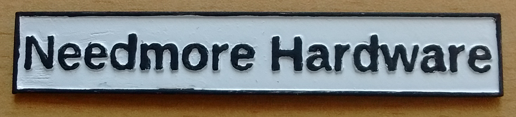
Now I’ll paint the letters (photo 11).
Well, this is not the best-looking sign that I have ever done, but it will still be going on my building. I am going to experiment with other methods of painting the sign. If you have any suggestions, please go to the subscriber extras at http://cs.trains.com/grw/f/91/t/254673.aspx and give me (and others) some pointers. I’ll be monitoring the site and am anxious to experiment to make better signs.
Extra signs!
I hope that you have found this useful and are now ready to give your railroad some signage. I have printed 25 “Needmore Hardware” signs at 1:20.32 scale and another 25 at 1:24 scale. I cannot use all these so, if you would like one, just email me at sberneberg@yahoo.com and I will send you a sign free of charge. They are cleaned up and had an acetone-vapor bath, so they should be ready for paint. Please specify the scale you are interested in and I will mail it out. Supplies are limited.