When I was young, I had an American Flyer train and a set of American Plastic Bricks (interlocking toy bricks made in the 1960s). I liked running the train, but I was particularly drawn to the bricks. I could easily build something, tear it down, and build something else.
Years later, I built an HO scale railroad. When I altered a completed scene, what I removed was often destroyed. I eventually dismantled the layout and went a number of years without any modeling hobby.
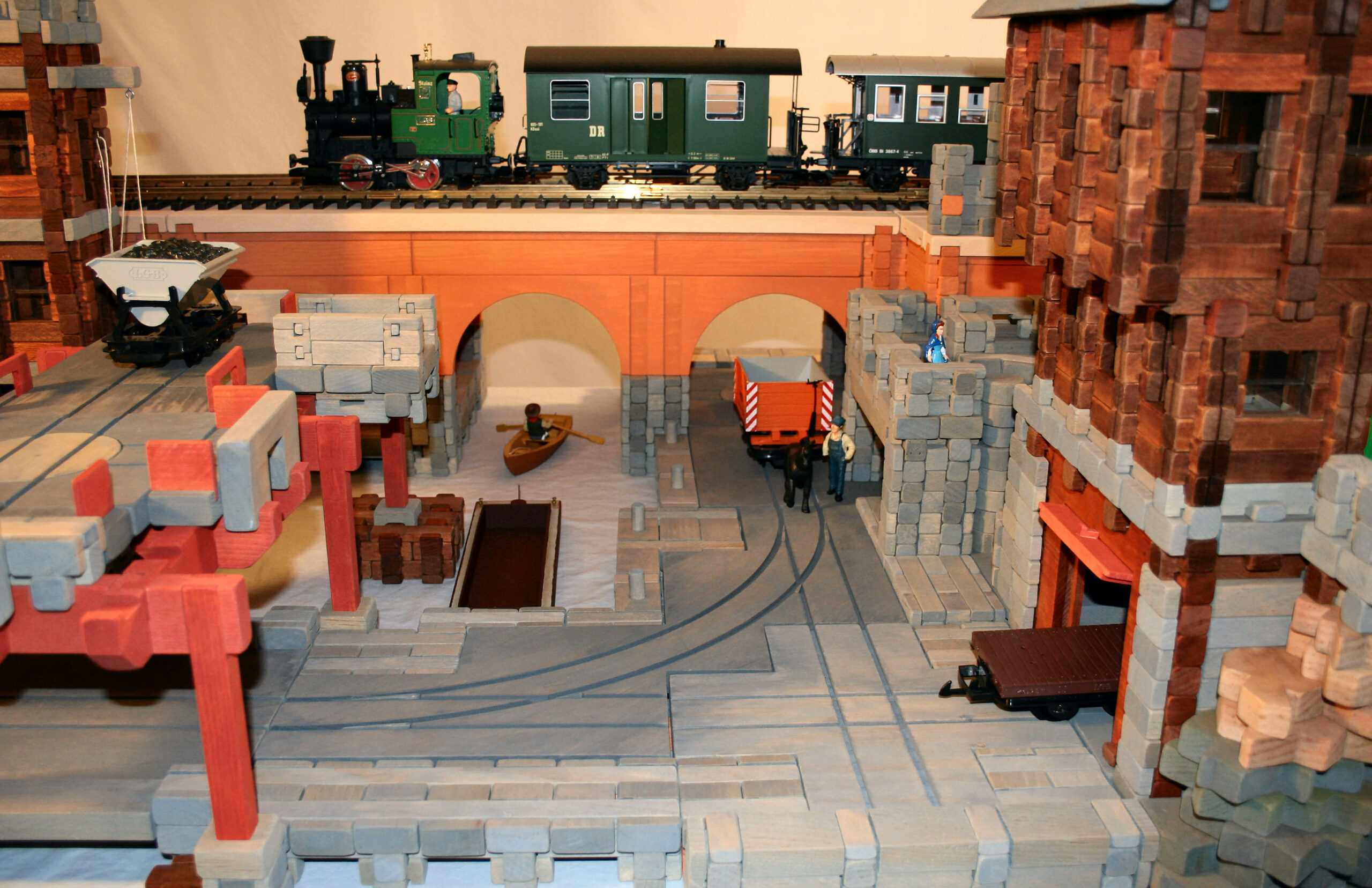
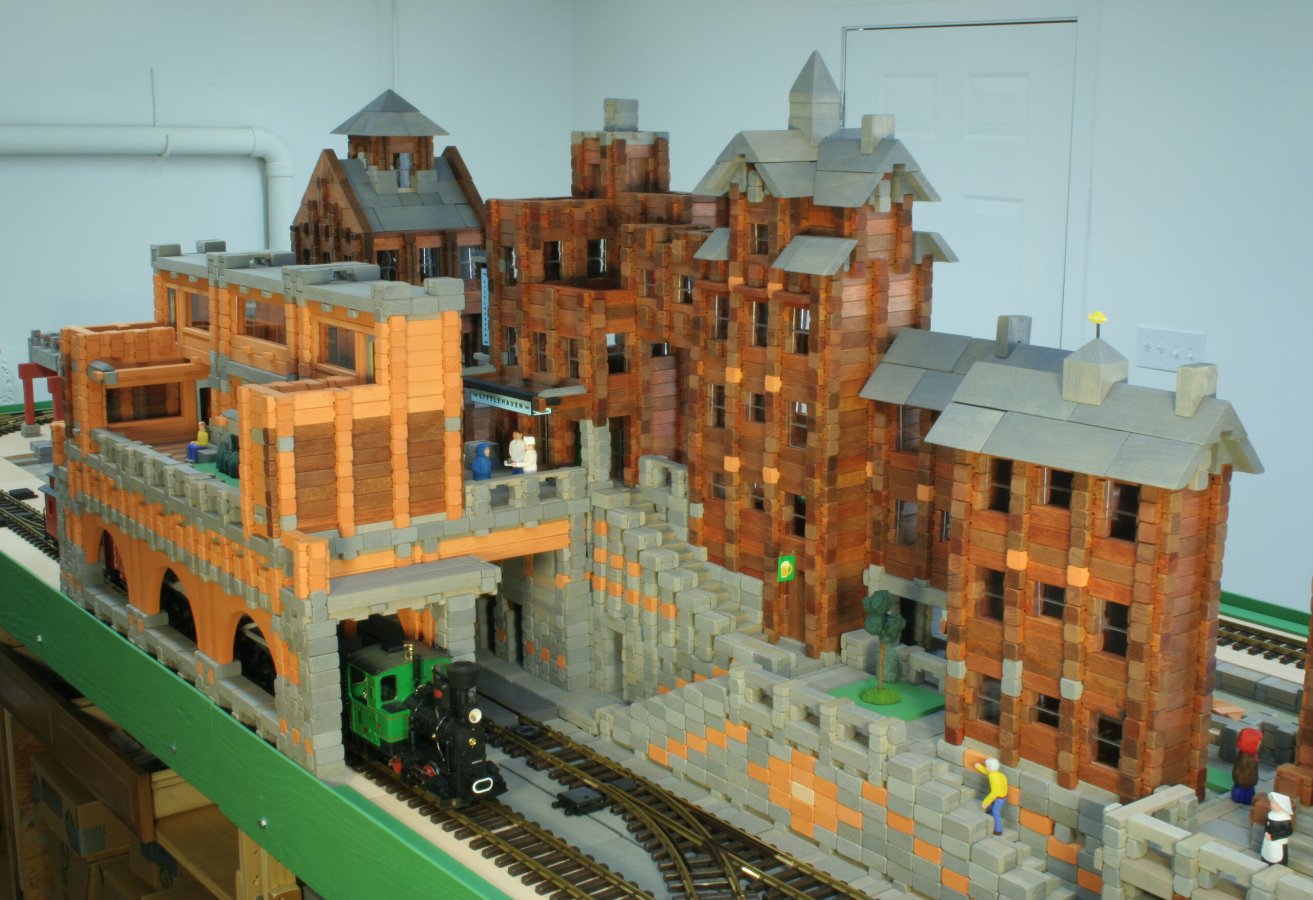
Whatever I made in the future had to be both touchable and reusable, more like a buildable “toy” than a model. When I decided to try model railroading again, I made what I call an elemental layout, using blocks and bricks to build scenes that weren’t permanent.
I created simple pieces (that I call blocks) from short lengths of wood, sort of a cross between my childhood American Plastic Bricks and American Logs toys. The basic dimensions for the blocks are a 1 1/2″ square, 3/4″ high piece that I call a unit.
I paint/stain the blocks different colors, such as gray for concrete, stained for wood, etc.
A “grid” is made up of a square with seven units on one side, with no height restriction. The small blocks and the supporting tables are multiples of a unit, and most of the larger blocks are multiples of a grid.
Tables
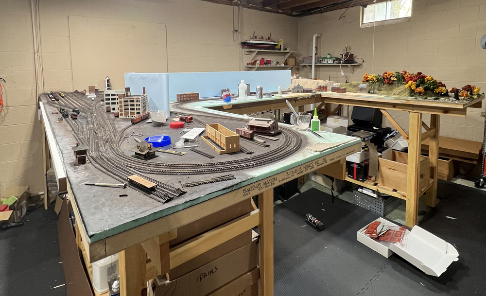
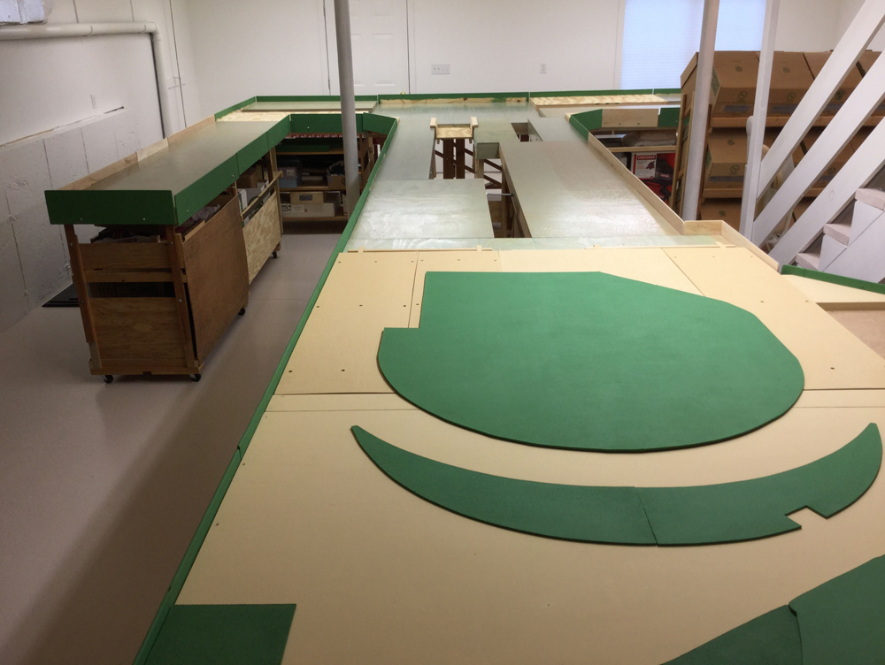
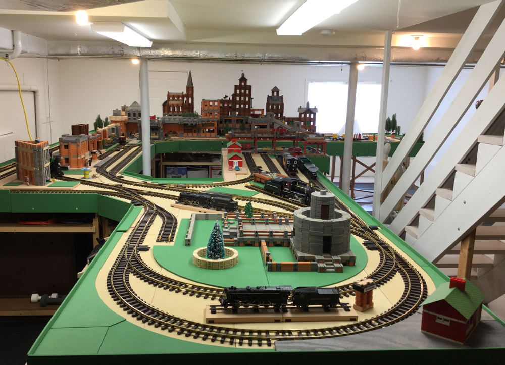
The tables consist of two parts: a top and a base. The tops are plywood sheets screwed to a supporting framework. I stained some of the tops a light green with a polyurethane coating to represent water; other tops are bare wood. The perimeter framework has 9/32″ holes every foot beginning 6″ from the ends to allow for 1/4″ bolts. The diagrams show the arrangement of tables (see PDF downloads at the end of the article).
The bases for the 2′ x 4′ and 2′ by 8′ tables are a framework of four posts with shelves on 2″ swivel castors. Some of the bases have one-piece posts; others have two-piece posts. The two-piece posts have 9/32″ holes every 1 1/2″, which are bolted together with 1/4″ bolts to allow for varying table heights. The tabletops rest on the posts but are not fastened to them.
The bases for the 1′ x 4′, 1′ x 8′ and 2′ x 2′ tables are braced legs with lag bolts on the bottom. These are bolted to the tabletop framework.
There are two sets of 2 1/2′ by 5′ tabletops bolted together for an LGB R1 radius circle. These rest on special bases with castors. There is also one odd shaped table that rests on three bookcases with castors, and a few 45 degree corner tops that bolt to other tables.
I bolt the tabletops together, then bolt fascia boards to the perimeter of the tabletops. The fascia keeps my brick/block constructions in place and help contain derailments. For odd offsets, I drill extra holes in the framework. For table height differences greater than the framework width, I make special brackets to connect the tabletops.
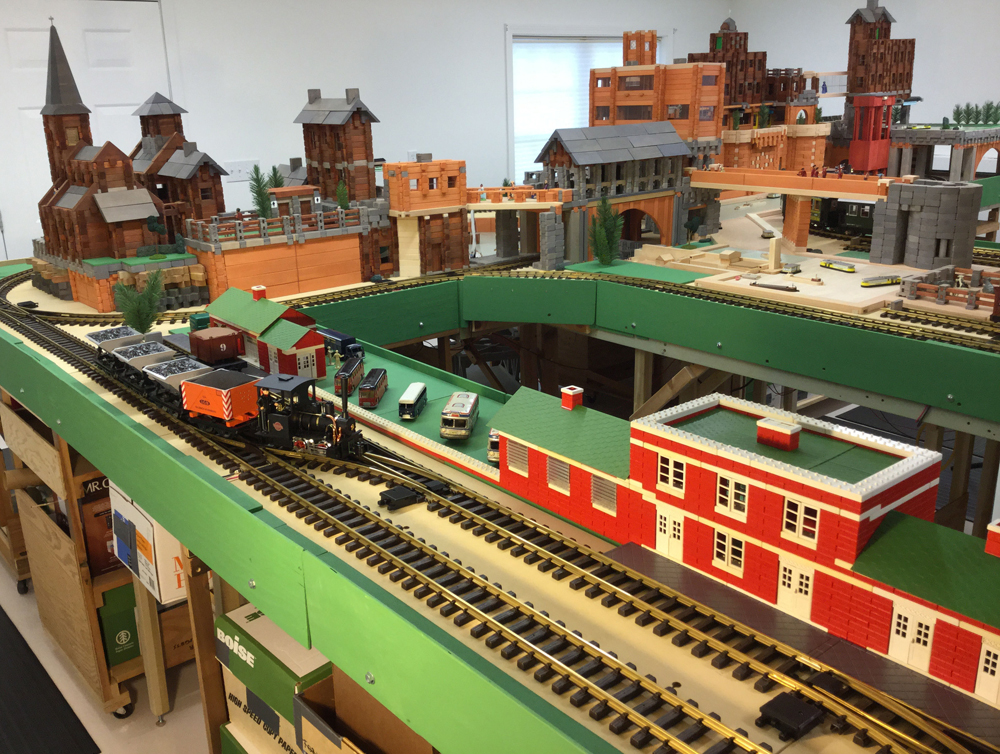
The track roadbed rests 1 1/8″ above the tabletops. This space allows for piers above water, for wires, and for structure bases. Greater depths require an open space between tables. Most block structures rest on blocks, and most track rests on loose, tan colored 1/4″ plywood sheets. The plywood sheets rest on long pine strips, some of which span any openings between tables.
Track
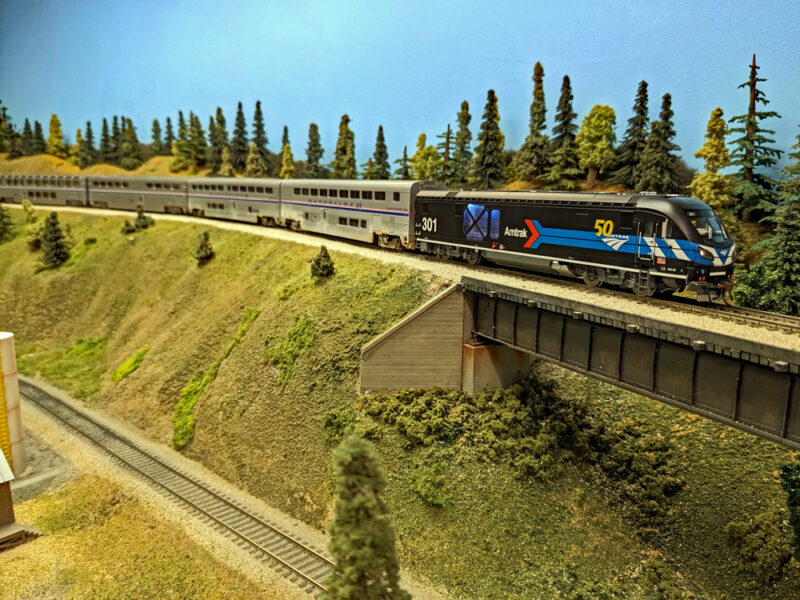
I use LGB sectional track with R1 radius curves. To be compatible with the blocks and the confines of the cellar, choose engines and rolling stock with short wheelbases. I use short and expandable track sections to avoid cutting rail. Split Jaw Rail Clamps replace rail joiners in every section so that track can be removed without pulling everything apart. [Split Jaw Rail Clamps have been discontinued. Trainli (https://www.trainli.com) and PIKO America (https://www.piko-america.com) also sell rail clamps for gauge-1 track. – Ed.]
When I design a new track plan, I place the sections without joiners together to avoid removing more joiners. Two switches for a reversing loop are powered and radio controlled; all others are manual. All the track plans are walk-around, and all the track is within two feet of the table’s edge for an easy reach.
Electricity
My locomotives are battery powered. Except for the turntable and reversing loop, the current layout has DC power for visiting locomotives. I designed terminal boards from a thin wood square with a hole in the center and two parallel brass strips with holes for small bolts. The terminal boards fit over long table bolts.
Wires of different lengths have ring terminals on each end either to connect two terminal boards or a terminal board to a rail clamp. Curtain rod rings with a pinch clip are secured to table bolts to carry the wires. A small control panel platform with two arms is bolted to the tables. This arrangement makes the minimal electrical wiring reusable.
Blocks
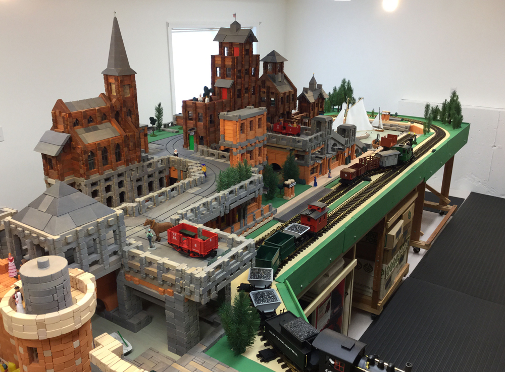
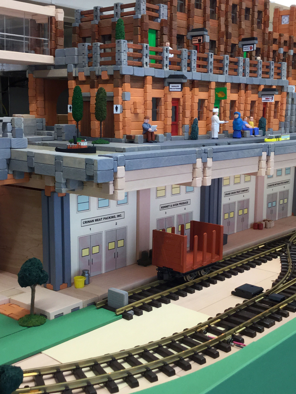
Except for the plywood track, which I secure to the roadbed only by the fascia boards, all my homemade blocks interlock. The primary interlocking method is log notches. The elemental nature of the blocks, tables, track and wiring easily allows for changes, updates, or modifications without destroying anything.
Downloads
Track and table diagram – 2006
The open area was covered by a 2′ x 4′ plywood sheet that rested on two parallel boards bolted to the framework of the table sides. See photo 2 in photo gallery. Illustration by Jim Covell
Track and table diagram – 2012.
See photos 3 and 4 in photo gallery. Illustration by Jim Covell
Track and table diagram – 2014
The open areas were covered by either blocks or plywood sheets that rested on long blocks. See photos 5 and 6 in photo gallery. Illustration by Jim Covell
Track and table diagram – 2016
The open areas are covered by either blocks or plywood sheets that rested on long blocks. See photos 1, 6-9 in photo gallery. Illustration by Jim Covell