


The initial goal of a new model railroader flush with locomotives, track, and rolling stock is to operate two trains on his layout at the same time, each with independent speed and direction control.
This milepost can be reached with cab-control wiring. With two direct- current power packs, single-pole double-throw toggle switches, and hardware-store wire, you can divide any layout into electrical blocks that will allow two trains to be operated independently.
How it works
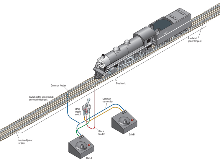
With cab-control wiring, a layout using two power packs is divided into several electrically isolated sections called “blocks.” One such block is shown in fig. 1. Each block is independent of all the others, so a train in block A can be operated by power pack A, and a train in block B can be run by power pack B.
Each block starts and ends with a plastic insulated rail joiner or a narrow gap cut through the metal rails. So while a cab control layout visually looks like a continuous track, electrically it’s several independent track sections that line up with one another at each end.
As an operator using power pack A moves his locomotive through one block and approaches the next block, he uses a toggle switch to connect the second block to power pack (cab) A. Now the two blocks are electrically united to cab A and the locomotive seamlessly moves from the first block to the second. Just before he enters a third block, he again connects the new block to cab A. Following this pattern, the operator can move his locomotive from one end of a layout to the other.
While this is occurring, a second operator using cab B can operate his locomotive elsewhere on the layout by connecting the blocks he’s using to cab B. In this manner, the two operators can follow each other around a layout, flipping toggle switches to align the blocks to cabs A or B as needed.
The only downside to cab control is that two locomotives cannot share the same block at the same time. Operator B has to wait until operator A has cleared a block in order to toggle control of the power in that block from cab A to cab B.
Single-pole double-throw (SPDT) electrical switches can connect only one cab to a block at a time, so there’s no way for both operators to connect their power packs to the same block at the same time. The only way to get into trouble is to run a train across the insulated rail joiners into another block connected to the other cab, so it’s important for operators to know exactly where one block ends and the next begins.
Blocks and wiring
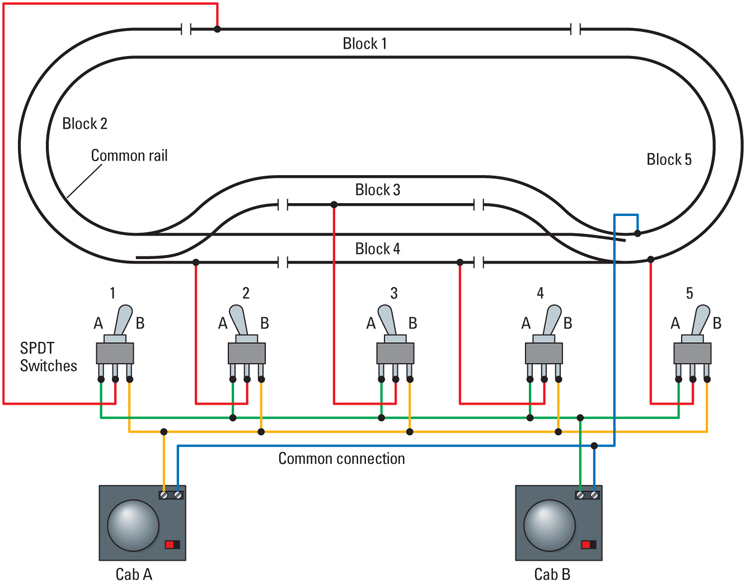
A layout at minimum needs three blocks for two trains, but more blocks give operators more flexibility. Fig. 2 on the next page shows wiring for a simple oval layout with one passing siding that’s been divided into five electrical blocks. Each block is controlled by its own SPDT toggle switch.
Some SPDT switches have a center off position that doesn’t connect power in either direction. This is especially useful for passing sidings (and spurs), since it allows you to cut power in that track to park a train.
It’s also smart to turn a block off after your train departs, or the next train that enters the block will be controlled by the wrong cab, leading to the cry “Someone’s got my train!”
Each block has a feeder wire connecting it to an SPDT switch. If a layout has six blocks it will need six SPDT switches.
When making track blocks, you need to insulate or cut a gap in just one rail, not both. Think of a light switch in your house. When you turn a lamp on or off, you are only interrupting one of the wires that lead to the lamp, not both.
In cab-control wiring, the rail that isn’t insulated or cut is called the common rail. This rail gets connected to both power packs. See the blue wire in fig. 2. While connecting two power packs in this manner may cause a bit of anxiety for a model railroader new to electricity, trust us, it works.
Also, by using a common rail, you save on wire, toggle switches, and soldering, since you’ll need to purchase only SPDT switches instead of the more expensive double-pole double-throw (DPDT) switches.
Most hardware stores sell toggle switches, and sometimes a hobby shop will sell electrical components (beyond wire) for model railroads. An alternative to toggle switches are Atlas’ Selectors, which are banks of four SPDT switches designed specifically for model railroads (see the next page), and using them doesn’t require soldering.
Power packs
The easiest way to build a cab-control layout is by using a pair of identical DC power packs. Figure 2 shows how to connect one track terminal from each power pack to the common rail on your layout. Keep in mind that your track configuration may shift the common rail from the inside of your layout to the outside. Follow the rail around your layout with your finger to be sure you have correctly identified the common rail so that you don’t break or “gap” it by mistake.
If you’re using two different power packs and mix up your wiring, it’ll create a short circuit and activate the power packs’ circuit breakers to cut power until the short is fixed. Don’t worry, though. As the breakers cool they’ll automatically restore the power once the short is fixed.
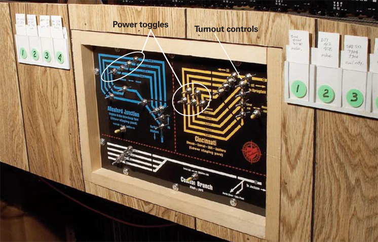
Cab control wiring can be as simple as fig. 2, or it can utilize many more blocks and power packs to let additional operators connect to a specific group of blocks on a large layout. The complex, color-coded control panel shown in fig. 3 operates three different staging yards on Jim Hediger’s Ohio Southern.
Cab control of model railroads has been around for decades, and that’s no surprise – it’s the best way to move from a single loop layout to more complex operation, short of entering the world of Digital Command Control.
How to wire a reverse loop
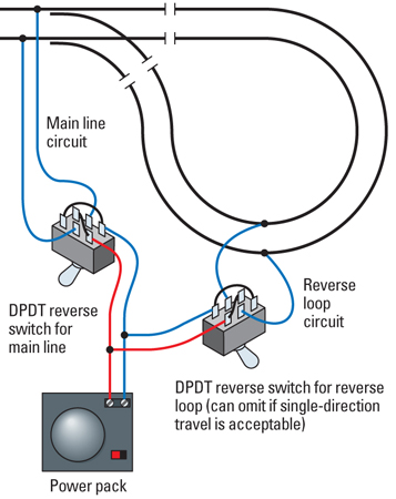
Any track configuration that permits a train to change its direction without simply backing up needs a special electrical circuit to prevent a short. Wiring a reverse loop, wye, or turntable may seem similar to block wiring, but there are some important differences.
The illustration shows basic reverse-loop wiring for a direct-current layout. This special situation requires double-pole double-throw (DPDT) toggle switches to change the polarity of the two rails in the reverse loop and in the track block preceding the loop. These DPDT switches allow an engineer to align the polarity of the rails so his train may enter or exit the reverse loop without causing a short circuit as it passes over the insulated rail joints.
If a train enters a track wye to turn around, insulated joints and a similar combination of two DPDT switches are needed to align the polarity so the train may leave the wye.
Combining cab-control wiring, reverse-loop wiring, and other wiring needs can quickly get complex. See fig. 3.
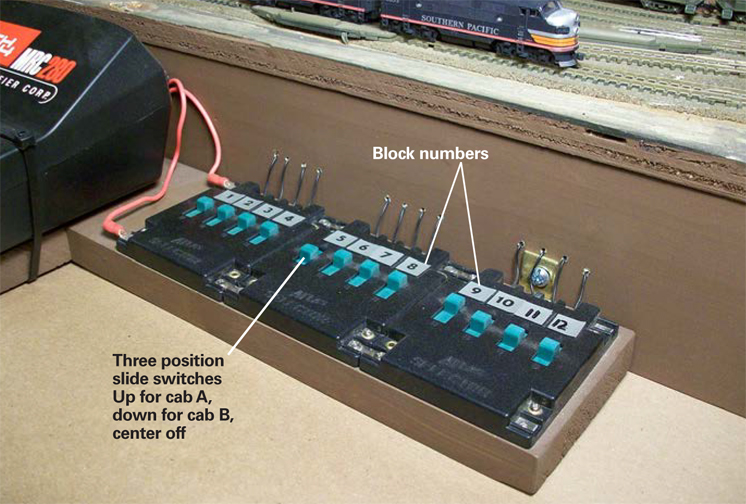
For many years Atlas has offered the no. 215 Selector, which is an inexpensive set of four single-pole double-throw (SPDT) slide switches for model railroad applications. Each Selector has screw connections and can be used with two power packs to operate four blocks. Selectors are designed to be used in multiples, so any number can be easily connected side-by-side (called ganging) to control any number of blocks, as shown above.
Like SPDT toggle switches, Selectors have three positions, a connection to power pack A, a center off position, and a connection to power pack B. The Selectors are even labeled A and B.
Atlas also makes a companion device called the no. 220 Connector, which contains three single-pole single-throw on/off SPST switches in the same housing.
Cab control terms
Block: A section of track on a layout that is electrically isolated from adjoining sections by use of plastic rail joiners or gaps cut in rails. Blocks can be any length – usually determined by a specific track plan.
Block switch: A single-pole double-throw (SPDT) electrical switch that’s used to connect one wire to either of two other wires. While most hobbyists think of toggle switches like those shown in figs. 1 and 2, slide and rotary switches can also have SPDT contacts. Some SPDT toggle switches are made with a center off position that does not connect to either wire.
Cab: Another name for a direct-current power pack with speed and direction controls to operate a train.
Cab control wiring: A method of wiring a model railroad using two or more power packs and track electrical blocks to allow independent operation of two or more trains.
Common rail: An electrically continuous rail that connects both power packs to complete the common electrical circuit. The other rail is called the “control rail” in which gaps are cut to define the electrical blocks.
Feeder: The wire connecting a segment of rail to the power supply.
Insulated rail joiner: A rail joiner made of an insulating material such as plastic instead of metal.

Hello. I am a newbie. Hope you bear with me. Am reading two-train operations using spdt switches and am not sure I understand what “cab a” and “cab b” are. Are they the ordinary wall adaptors? Thanks
when you wire a layout in Z, N Scale, or HO you use the wire that your scale needs or you risk going over amps. Z, N, and HO use 14, 18, 20, and 22 gauge wire which is stranded and can plug into any DC powerpack or command station. What not to use 12 gauge wire 12 gauge wire is only suppose to used outdoors and it has a nickel core and your need pliers to bend it. the problem with 12 gauge wire is it will snap if you bend it and if you hook it to a powerpack and you don’t have a resistor or transformer on the end your accessories and locomotives will overload and you will be left with melted electronics because it has more amps. Only use 12 if you need to make a long run and between two breakers do not connect it to your tracks only use stranded to connect to the track bus. Example if your layout is N Scale use 22 for the connectors and 20 or 18 for the bus 14 for longer runs. if you have Z same as N but use 18 for longer runs HO use 20 and 18 use 14 for longer runs or go with 12 for the breakers.
I have a small layout and stuck with one train at a time. Can’t afford DCC do to budget, so this is a great article for people like me that are sticking with the old DC control.
Good article. I am new to HO. I am planning a layout with 14, maybe 16 switches using three Marklin engines. The system will be controlled using AC. Are there any MR books/magazines describing AC.
I am new to model RR. I am looking for more info on reverse loop wiring for my dcc kato unitrack lay-out. very confused on this aspect of wiring. any added help will be of great help. thanks
Where can I find a wiring diagram for a reverse loop using two-cab control? Figure 2 shows cab control, and another figure shows the reverse loop, but how do I combine them? Can one (or both) of the polarity-changing toggles be combined with the cab-selector toggle?
Hi – nice article with clear explanations. Just one comment – are the A and B designations on Figure 2 reversed? Seems like the toggle switch in the "B" position would be controlled by Cab "A". Maybe I'm just confused … thanks for the article.
Thank you Neil for this refresher. There are still plenty of modelers using conventional DC (and indeed a case can be made that this might be the time for the fence-sitters to wait out the refinements of DCC in anticipation of the next advance which is certain to come sooner than you'd think: battery powered, radio controlled).
What is needed is a new edition of Andy Sperandeo's Easy Wiring book (which I am surprised has been allowed to go out of print) tailored for people who are sticking with DC, for now, and who know what DCC is and what it can do. At this point his entire chapter on DCC could probably be replaced with a few paragraphs. The suppliers for DC and electronics in general have either changed (rarely for the better) and there are some fringe suppliers who could be included.
Also it is evident from the Forums discussions that there remains a great deal of uncertainty and confusion about Peco and its turnouts in particular, which Andy only touches on in his book.